Product Description
Product Description
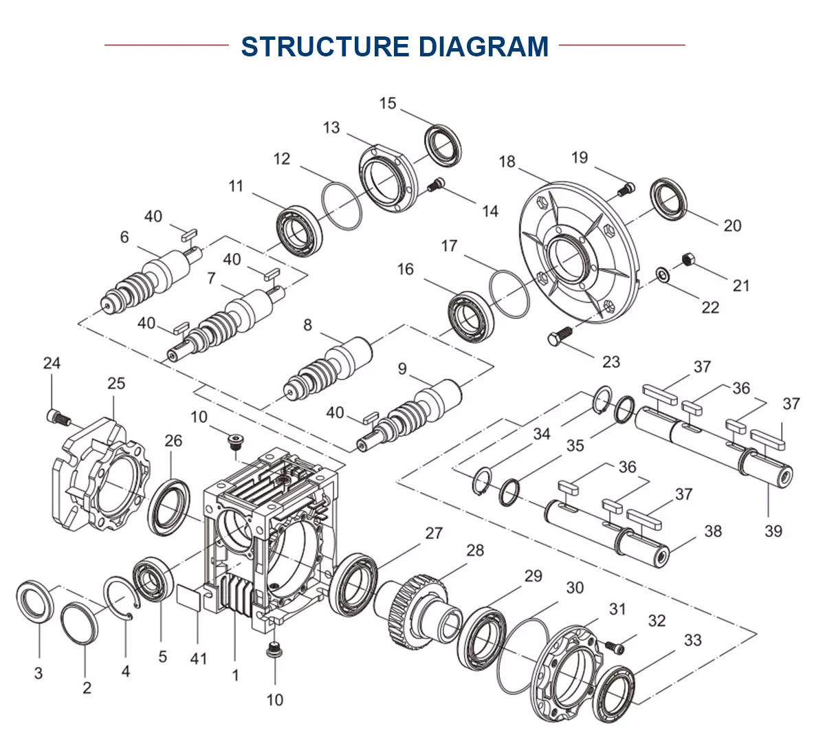
Slewing drive is a full cycle rotary reduction transmission mechanism that integrates a driving power source. It uses a rotary bearing as the driving follower and mechanism attachment, and attaches an active component, driving source, and cover to 1 of the inner and outer rings of the rotary bearing. The other ring is used as both the driving follower and the connecting base of the driven working component. This makes use of the characteristic that the rotary bearing itself is a full cycle rotary connection, Efficiently configuring the driving power source and main transmission components, making it a universal deceleration transmission mechanism that integrates rotation, deceleration, and driving functions, while also having a simple structure and easy manufacturing and maintenance.
Product Parameters
| Name | Code | Unit | Value | Name | Code | Unit | Value | |
| Module | m | mm | 3 | Module | m | mm | 5 | |
| Reduction ratio | i | – | 77:1 | Reduction ratio | i | – | 62:1 | |
| Raceway diameter | Do | mm | 162 | Raceway diameter | Do | mm | 222.5 | |
| Overturning moment | M | N.m | 13600 | Overturning moment | M | N.m | 26300 | |
| Torque | Ma | N.m | 1500 | Torque | Ma | N.m | 3850 | |
| Weight | W | Kg | 25 | Weight | W | Kg | 59 |
| Name | Code | Unit | Value | Name | Code | Unit | Value | |
| Module | m | mm | 3 | Module | m | mm | 5 | |
| Reduction ratio | i | – | 62:1 | Reduction ratio | i | – | 83:1 | |
| Raceway diameter | Do | mm | 224 | Raceway diameter | Do | mm | 315 | |
| Overturning moment | M | N.m | 26300 | Overturning moment | M | N.m | 51800 | |
| Torque | Ma | N.m | 3850 | Torque | Ma | N.m | 8100 | |
| Weight | W | Kg | 59 | Weight | W | Kg | 85 |
| Name | Code | Unit | Value | Name | Code | Unit | Value | |
| Module | m | mm | 5 | Module | m | mm | 5 | |
| Reduction ratio | i | – | 88:1 | Reduction ratio | i | – | 88:1 | |
| Raceway diameter | Do | mm | 335 | Raceway diameter | Do | mm | 342.5 | |
| Overturning moment | M | N.m | 75100 | Overturning moment | M | N.m | 67800 | |
| Torque | Ma | N.m | 8600 | Torque | Ma | N.m | 8600 | |
| Weight | W | Kg | 93 | Weight | W | Kg | 87 |
| Name | Code | Unit | Value | Name | Code | Unit | Value | |
| Module | m | mm | 5 | Module | m | mm | 5 | |
| Reduction ratio | i | – | 106:1 | Reduction ratio | i | – | 106:1 | |
| Raceway diameter | Do | mm | 422.5 | Raceway diameter | Do | mm | 425 | |
| Overturning moment | M | N.m | 131500 | Overturning moment | M | N.m | 132600 | |
| Torque | Ma | N.m | 12800 | Torque | Ma | N.m | 12800 | |
| Weight | W | Kg | 119 | Weight | W | Kg | 121 |
Company Profile
HangZhou solarich machinery Co., Ltd. is a professional manufacturer of bearings, We can design and manufacture single-row ball slewing bearings, double-row ball slewing bearings, three-row roller slewing bearings, ball combination slewing bearings, crossed roller bearings, crossed tapered roller bearings Bearings, slewing drives and custom bearings.
The company has 1 of the earliest group of R & D, design and manufacturing personnel who apply slewing drive to various mechanical products. In construction machinery, we have experienced rich practice and accumulated valuable experience in the application of slewing drive in engineering machinery, mining machinery, agricultural machinery, and specialized vehicles.
Adhering to the business philosophy of “Quality and Integrity”, we will continue to provide excellent bearings and high-quality services to serve global customer.
Solutions
Packaging & Shipping
FAQ
Q: Are you trading company or manufacturer?
A: We are bearing manufacturer.
Q: What is the MOQ?
A: It depends on the bearing type. You can send inquiry or send e-mail for more information.
Q: How about the package?
A: Industrial packing in general condition (Plastic tube+ carton+ pallet). Accept design package when OEM.
Q: How long is the delivery time?
A: It will take about 10 to 40 days, depends on the model and quantity.
Q: How about the shipping?
A: We can arrange the shipment or you may have the forwarder.
Q: Is sample avaiable?
A: Yes, sample order is acceptable.
Q: Can we use our own LOGO or design on bearings?
A: Yes. OEM is acceptable. We can design the bearing with your requirements and use your own LOGO and package design.
/* January 22, 2571 19:08:37 */!function(){function s(e,r){var a,o={};try{e&&e.split(“,”).forEach(function(e,t){e&&(a=e.match(/(.*?):(.*)$/))&&1
| Feature: | High Speed, Cold-Resistant, Corrosion-Resistant, Heat-Resistant |
|---|---|
| Step: | Single-Step |
| Layout: | Three-Ring |
| Samples: |
US$ 1/Piece
1 Piece(Min.Order) | Order Sample |
|---|
| Customization: |
Available
| Customized Request |
|---|
.shipping-cost-tm .tm-status-off{background: none;padding:0;color: #1470cc}
| Shipping Cost:
Estimated freight per unit. |
about shipping cost and estimated delivery time. |
|---|
| Payment Method: |
|
|---|---|
|
Initial Payment Full Payment |
| Currency: | US$ |
|---|
| Return&refunds: | You can apply for a refund up to 30 days after receipt of the products. |
|---|
What are the costs associated with installing and maintaining gear drives?
The installation and maintenance of gear drives involve various costs. Here’s a detailed explanation:
1. Initial Installation Costs:
– The initial installation costs include the purchase of gear drives and any additional components required for installation.
– The cost of gear drives can vary depending on factors such as gear type, size, quality, and manufacturer.
– Additional installation costs may include materials, labor, equipment, and any necessary modifications to the existing machinery or systems.
2. Maintenance and Inspection Costs:
– Regular maintenance and inspection are essential for ensuring the optimal performance and longevity of gear drives.
– Maintenance costs may include expenses related to lubrication, cleaning, and adjustments.
– Inspection costs can involve the use of specialized tools, equipment, or professional services to assess gear drive conditions and identify any potential issues.
3. Replacement and Repair Costs:
– Over time, gear drives may experience wear, damage, or failure, requiring replacement or repair.
– Replacement costs involve the purchase of new gear drives or specific components, such as gears or bearings.
– Repair costs may include labor, replacement parts, or the engagement of specialized repair services.
4. Downtime and Production Losses:
– Gear drive maintenance or replacement activities can result in downtime, leading to production losses.
– Downtime costs can vary depending on the industry, production rates, and the criticality of the gear drive in the overall operation.
– Minimizing downtime through efficient maintenance planning and scheduling can help mitigate production losses.
5. Training and Expertise:
– Proper maintenance of gear drives may require trained personnel with specific knowledge and expertise.
– Costs associated with training programs, certifications, or hiring skilled maintenance technicians should be considered.
– In some cases, companies may choose to outsource gear drive maintenance to specialized service providers, incurring additional costs.
6. Lifecycle Costs:
– Gear drives have a finite lifespan, and considering their lifecycle costs is essential.
– This includes the cumulative costs associated with installation, maintenance, repairs, replacements, and eventual decommissioning or disposal.
– Evaluating the lifecycle costs helps in making informed decisions regarding gear drive selection, maintenance strategies, and overall cost-effectiveness.
It’s important to note that the costs associated with installing and maintaining gear drives can vary significantly depending on factors such as the complexity of the system, the size and type of gear drives, the operating conditions, and the specific industry requirements. Implementing proactive maintenance practices, adhering to manufacturer recommendations, and monitoring gear drive performance can help optimize costs and maximize the operational efficiency and reliability of gear drive systems.
How are gear drives used in renewable energy applications?
Gear drives play a crucial role in various renewable energy applications. Here’s a detailed explanation:
1. Wind Turbines:
– Gear drives are widely used in wind turbines to convert the low-speed rotation of the turbine blades into high-speed rotation suitable for generating electricity.
– The gear drives amplify the rotational speed, allowing the generator to operate at the required speed to produce electricity efficiently.
2. Solar Tracking Systems:
– In solar tracking systems, gear drives are employed to adjust the position of solar panels or mirrors to maximize the capture of solar energy.
– The gear drives enable precise and controlled movement of the panels or mirrors, aligning them with the sun’s position throughout the day for optimal energy collection.
3. Hydroelectric Power Plants:
– Gear drives are utilized in hydroelectric power plants to convert the slow rotational motion of the turbine into high-speed rotation for power generation.
– The gear drives increase the rotational speed and transmit the power to the generator, which converts the mechanical energy into electrical energy.
4. Tidal and Wave Energy Converters:
– Gear drives are employed in tidal and wave energy converters to increase the rotational speed of the turbine or generator system.
– They help convert the relatively slow and irregular motion of the tides or waves into a higher-speed rotation suitable for electricity generation.
5. Geothermal Power Plants:
– Gear drives are utilized in geothermal power plants to transmit power from the geothermal turbine to the generator for electricity production.
– They enable the conversion of the low-speed, high-torque rotational motion of the turbine into high-speed rotation required by the generator.
6. Biomass Energy Systems:
– Gear drives are used in biomass energy systems to convert the rotational motion of the biomass combustion engine or steam turbine into high-speed rotation for electricity generation.
– The gear drives help optimize the rotational speed and torque characteristics of the system for efficient power production.
Overall, gear drives are essential components in renewable energy applications, enabling the efficient conversion of various natural energy sources into usable electricity. They help amplify rotational speed, adjust positions for optimal energy capture, and transmit power from turbines to generators. By facilitating the effective utilization of renewable energy sources, gear drives contribute to the growth and sustainability of clean and renewable energy generation.
How do you choose the right gear drive for a specific application?
Choosing the right gear drive for a specific application requires careful consideration of various factors. Here’s a detailed explanation of the key considerations in selecting the appropriate gear drive:
1. Load Requirements:
– Determine the magnitude and type of the load the gear drive will need to transmit.
– Consider factors such as torque, speed, and any shock or impact loads.
– Select a gear drive with the load capacity and durability to handle the specific load requirements.
2. Speed and Torque Requirements:
– Analyze the desired speed and torque characteristics of the application.
– Consider the required speed reduction or increase and the torque multiplication or reduction.
– Choose a gear drive with the appropriate gear ratio to achieve the desired speed and torque output.
3. Space Constraints:
– Evaluate the available space for installing the gear drive.
– Consider the dimensions and configuration of the gear drive, including the shaft orientation and mounting options.
– Select a gear drive that fits within the space limitations without compromising performance or accessibility.
4. Efficiency:
– Assess the desired efficiency and energy requirements of the application.
– Different types of gear drives have different levels of efficiency.
– Consider the efficiency of the gear drive and balance it with other performance factors.
5. Noise and Vibration:
– Evaluate the noise and vibration limitations of the application.
– Some gear drives, such as helical gears, offer quieter and smoother operation compared to others.
– Consider the noise and vibration characteristics of the gear drive to ensure it meets the application’s requirements.
6. Maintenance and Reliability:
– Consider the desired maintenance schedule and reliability expectations.
– Evaluate factors such as lubrication requirements, maintenance access, and expected lifespan.
– Choose a gear drive that aligns with the maintenance and reliability goals of the application.
7. Cost:
– Assess the budget constraints and cost-effectiveness of the gear drive.
– Consider the initial investment cost, maintenance costs, and potential savings in energy efficiency.
– Select a gear drive that provides the best balance between performance and cost for the specific application.
By carefully considering these factors and understanding the specific requirements of the application, it becomes possible to choose the right gear drive that meets the performance, space, efficiency, reliability, and budget needs. Consulting with gear drive manufacturers or industry experts can also provide valuable guidance in the selection process.


editor by Dream 2024-05-16
China supplier Solar Tracker Slewing Drive Gear Motor bevel gear set
Product Description
CHINAMFG Drive SC9 slewing drive gear motor worm gear for 18-32 square meter solar tracker system.
Slewing drive motor for single and dual axis solar plant,PV and CSP system.
|
Model |
SC9 |
IP |
IP65 |
|
Brand |
Coresun Drive |
Available Load Weight |
500-800kg |
|
IP Class |
IP65 |
Output Torque |
854N.m |
|
Tilting Moment Torque |
33.9KN.m |
Holding Torque |
38.7KN.m |
|
Mounting Bolts |
M16 |
Electrial Motor |
24VDC |
|
Gear Ratio |
61:1 |
Efficiency |
40% |
Coresun Drive Equipment HangZhou Co., Ltd. Slewing drives function with standard worm technology, in which the worm on the horizontal shaft acts as the driver for the gear. The rotation of the horizontal screw turns a gear about an axis perpendicular to the screw axis. This combination reduces the speed of the driven member and also multiplies its torque; increasing it proportionally as the speed decreases. The speed ratio of shafts depends CHINAMFG the relation of the number of threads on the worm to the number of teeth in the worm wheel or gear.
Coresun Slewing Drive movement can reduce power consumption, since the security role. In addition to the field of use in the daily solar power systems are usually used for Special vehicle, heavy-duty flat-panel truck, container cranes, truck mounted crane, automobile crane and aerial vehicles, cranes, gantry cranes, small wind power stations, space communications, satellite receiver, etc…The Slewing Drive in the solar photovoltaic industry, the general configuration DC planetary reduction motor or AC geared motors; Main configuration of the hydraulic motor as a power-driven construction machinery
Coresun Slewing Drive principle of the large transmission ratio of the deceleration device to transmit motion and power between the 2 axes staggered in space. The Slewing Drive transmission is usually the case of the main components of the worm and wheel bearings, shell, and the power source
Slewing drive is a special bearing. And a slewing drive usually consist of slewing bearing, worm shaft, housing, bearing, motor and so on. Motor drive the worm shaft, the outer ring of slewing bearing will rotate, the outer ring output the torque through flange while the inner ring of slewing bearing is fixed in housing.Coresun Slewing Drive and rotary products, compared with the ease of installation, ease of maintenance, Installation space savings advantages to a greater extent.
Slewing drives are widely used in aerospace area, solar power systems, wind turbines, satellite broadcasting system, and engineering machinery like truck cranes, and man lifts, etc. Recently years, it has been prosperously used in photovoltaic power generation systems, special vehicle, heavy-duty flat-panel truck, container cranes, truck mounted crane, automobile crane and aerial vehicles, cranes, gantry cranes, small wind power stations, space communications, satellite receiver, etc.
Why Choose Us:
Solar heliostat tracking system is a mechanical and electronic control unit system which optimizes the use of sunlight to improve photoelectric conversion efficiency in the process of photothermal and photovoltaic power generation. It mainly includes photovoltaic applications and photothermal applications.
1. Our manufacturing standard is according to machinery standard JB/T2300-2011, we also has been found the efficient Quality Management Systems(QMS) of ISO 9001:2015 and GB/T19001-2008.
2. We devote ourselves to the R &D of customized slewing bearing with high precision,special purpose and requirements.
3. With abundant raw materials and high production efficiency, the company can supply products to customers as quickly as possible and shorten the time for customers to wait for products.
4. Our internal quality control includes first inspection, mutual inspection, in-process quality control and sampling inspection to ensure product quality. The company has complete testing equipment and advanced testing method.
5. Strong after-sales service team, timely solve customer problems, to provide customers with a variety of services.
6. Delivery Time: 7 days after
7. Warranty Time: 5 years
8. ISO and CE certificate for quality guarantee
Coresun Drive Slewing Drive Motor Production Photo and Application
CHINAMFG Drive processes the metallography detection to check the material and organization structure of worm shaft,slewing gear and casting housing.
Coresun Drive testing reports for slewing bearing,worm shaft and finished slewing drive
CONTACT US
It is sincerely looking CHINAMFG to cooperating with you for and providing you the best quality product & service with all of our heart!
/* January 22, 2571 19:08:37 */!function(){function s(e,r){var a,o={};try{e&&e.split(“,”).forEach(function(e,t){e&&(a=e.match(/(.*?):(.*)$/))&&1
| Condition: | New |
|---|---|
| Certification: | ISO, CE |
| Application: | Industrial |
| Specification: | Normal, SC9-61-RC-24H15300-RV. A |
| Holding Torque: | 38.7kn.M |
| Tilting Moment Torque: | 33.9kn.M |
| Customization: |
Available
| Customized Request |
|---|
How do gear drives work in robotic and automated systems?
Gear drives play a crucial role in robotic and automated systems by transmitting motion and power between different components. Here’s a detailed explanation of how gear drives work in these systems:
1. Power Transmission:
– In robotic and automated systems, gear drives are used to transmit power from motors to various mechanical components.
– Electric motors provide rotational motion, which is converted into linear or angular motion by the gear drive.
– The gear drive consists of a set of gears with different sizes and configurations that mesh together to transfer torque and speed.
2. Speed and Torque Conversion:
– Gear drives allow for the conversion of speed and torque between the motor and the driven components.
– By using gears with different sizes (varying number of teeth), the gear drive can change the rotational speed and torque output.
– For example, a gear drive with a larger gear driving a smaller gear will increase the torque while reducing the speed, and vice versa.
3. Motion Control:
– Gear drives enable precise motion control in robotic and automated systems.
– By selecting the appropriate gear ratio, the gear drive can control the speed and position of the driven components.
– Gear drives can be used to achieve smooth and accurate movements, such as in robot arms, conveyor systems, or CNC machines.
4. Reducing Inertia:
– Inertia refers to an object’s resistance to changes in motion.
– Gear drives can help reduce the overall inertia in robotic and automated systems.
– By using smaller gears, the gear drive can reduce the inertia of the driven components, allowing for faster and more responsive movements.
5. Backlash Compensation:
– Backlash refers to the slight play or clearance between gear teeth, which can result in a loss of accuracy and precision.
– Gear drives in robotic and automated systems often incorporate backlash compensation mechanisms to minimize this issue.
– These mechanisms can include preloading the gears or using anti-backlash gears to eliminate or reduce the effects of backlash.
6. Load Distribution:
– In complex robotic systems, multiple gear drives are often used to distribute the load and share the torque among different components.
– This distribution of load helps prevent overloading of individual gear drives and ensures a balanced operation of the system.
7. Redundancy:
– Some robotic and automated systems incorporate redundant gear drives to enhance reliability and fault tolerance.
– Redundant gear drives can provide backup functionality in case of failure or allow for continued operation with reduced performance in the event of a single gear drive failure.
Overall, gear drives are essential components in robotic and automated systems, enabling power transmission, motion control, speed and torque conversion, and load distribution. The specific design and configuration of gear drives in these systems depend on the application requirements, desired performance, and system constraints.
How are gear drives used in renewable energy applications?
Gear drives play a crucial role in various renewable energy applications. Here’s a detailed explanation:
1. Wind Turbines:
– Gear drives are widely used in wind turbines to convert the low-speed rotation of the turbine blades into high-speed rotation suitable for generating electricity.
– The gear drives amplify the rotational speed, allowing the generator to operate at the required speed to produce electricity efficiently.
2. Solar Tracking Systems:
– In solar tracking systems, gear drives are employed to adjust the position of solar panels or mirrors to maximize the capture of solar energy.
– The gear drives enable precise and controlled movement of the panels or mirrors, aligning them with the sun’s position throughout the day for optimal energy collection.
3. Hydroelectric Power Plants:
– Gear drives are utilized in hydroelectric power plants to convert the slow rotational motion of the turbine into high-speed rotation for power generation.
– The gear drives increase the rotational speed and transmit the power to the generator, which converts the mechanical energy into electrical energy.
4. Tidal and Wave Energy Converters:
– Gear drives are employed in tidal and wave energy converters to increase the rotational speed of the turbine or generator system.
– They help convert the relatively slow and irregular motion of the tides or waves into a higher-speed rotation suitable for electricity generation.
5. Geothermal Power Plants:
– Gear drives are utilized in geothermal power plants to transmit power from the geothermal turbine to the generator for electricity production.
– They enable the conversion of the low-speed, high-torque rotational motion of the turbine into high-speed rotation required by the generator.
6. Biomass Energy Systems:
– Gear drives are used in biomass energy systems to convert the rotational motion of the biomass combustion engine or steam turbine into high-speed rotation for electricity generation.
– The gear drives help optimize the rotational speed and torque characteristics of the system for efficient power production.
Overall, gear drives are essential components in renewable energy applications, enabling the efficient conversion of various natural energy sources into usable electricity. They help amplify rotational speed, adjust positions for optimal energy capture, and transmit power from turbines to generators. By facilitating the effective utilization of renewable energy sources, gear drives contribute to the growth and sustainability of clean and renewable energy generation.
How do you calculate the gear ratio in a gear drive?
Calculating the gear ratio in a gear drive involves determining the relationship between the number of teeth on the driving gear (pinion) and the number of teeth on the driven gear. Here’s a detailed explanation:
The gear ratio is defined as the ratio of the number of teeth on the driven gear to the number of teeth on the driving gear. It represents the speed or torque multiplication or reduction achieved by the gear drive.
The gear ratio (GR) can be calculated using the following formula:
GR = Number of teeth on driven gear / Number of teeth on driving gear
For example, consider a gear drive with a driving gear (pinion) having 20 teeth and a driven gear having 60 teeth. The gear ratio can be calculated as follows:
GR = 60 (driven gear) / 20 (driving gear) = 3
In this case, the gear ratio is 3:1, indicating that for every three revolutions of the driving gear, the driven gear completes one revolution. This represents a speed reduction, with the driven gear rotating at one-third the speed of the driving gear.
It’s important to note that the gear ratio can be expressed in different formats, such as a decimal, fraction, or as a ratio. The choice of representation depends on the specific requirements and conventions of the gear drive application.
Additionally, it’s worth mentioning that gear drives can have multiple gears arranged in series or parallel, forming gear trains. In such cases, the overall gear ratio is calculated by multiplying the individual gear ratios of each gear pair in the train.
When designing or selecting gear drives, calculating the gear ratio is essential for determining the speed reduction or increase and torque amplification provided by the gear system. It enables engineers and designers to match the gear drive to the desired operational requirements of the mechanical system.
editor by Dream 2024-05-16
China high quality Dual Axis Solar Tracker Slewing Drive Gear Motor bevel spiral gear
Product Description
SVH3 dual axis slewing drive slewing bearing is available to 3-10 square meter solar tracker system
|
Model |
SVH3 |
Place of Origin |
HangZhou,China |
|
Brand |
Coresun Drive |
Type |
Dual Axis |
|
IP Class |
IP65 |
Output Torque |
446N.m |
|
Tilting Moment Torque |
1100N.m |
Holding Torque |
2000N.m |
|
Mounting Bolts |
M10 |
Output Speed |
1rpm |
|
Gear Ratio |
62:1 |
Efficiency |
40% |
Coresun Drive is a professional manufacturer and exporter of slewing bearing/slewing ring/slew circle, slewing drives/slew drive, which are mainly applied in port machinery, mining machinery, welding machinery, construction vehicles, modular vehicles, single or dual axis solar tracking systems, and small wind power systems etc.
The slewing drive is a new type of slewing product, usually called slewing ring, which is usually composed of worm, slewing ring, housing, motor and other components. Since the core components are slewing bearings, they can simultaneously withstand axial forces, radial forces, and overturning moments. Compared with traditional rotary products, the new slewing drive features easy installation, easy maintenance and a greater degree of installation space.
Slewing drive are widely used in PV,CPV,STP solar tracking systems and construction applications including truck cranes, manlifts, turntables, port machinery, modular vehicles, small wind power systems and satellite communications.
Product Advantage:
Slew drives are ready-to-mount modules which are capable of transmitting forces and high torques. CHINAMFG Drive slew drives consist of a ball bearing and a worm screw enclosed by a housing structure.
The enclosed housing guarantees a sustainable, low-maintenance operation without loss of lubrication, as well as protection against environmental influences.
1-3m Dia.TVRO dish dual axis slewing drive slewing gear
Higher tracking precision
IP class 65
Temperature range: -30ºC-60ºC
High Transmission Efficiency
High impact resistance
SVH3 dual axis slewing drive slewing bearing is available to 3-10 square meter solar tracker system.
For 4-6pcs solar panels tracking design
For 1-2.5 Dia. satellite receiver and solar dish system
1, What are the differentiates between CHINAMFG with other supplier?
Profession and reliability.
Our advantages are multiple available technologies, strong quality assurance, and good at project & supply chain management.
2, Is there a cost for CHINAMFG service?
There is no additional cost above the product and tooling price except third party service.
3, Will I be able to visit the supplier myself?
First, all of our supply partner has undergone a series of screening and audit process, we can provide complete audit report to you.
Secondly, if you want to perform your own independent supplier audit procedure, our representatives can accompany and assistant with you to achieve it.
4, How to deal with the quality problem?
A. With our partners we perfom APQP at early stage in each project.
B. Our factory must fully understand the quality concerns from customers and implement product & process quality requirements.
C. Our quality professionals who perfom patrol inspection in our factories.
We perform final inspectors before the goods are packed.
D. We have 3rd party inspectors who perform final audit checks on the packed goods prior to dispatch from China.
5, Can you take responsibility for me?
Of course, I’m happy to help you! But I just take responsitility fo my products.
Please offer a test report.
If it was our fault, absolutely we can make a compensation for you, my friend!
6, Do you like to serve the client only with small order?
We enjoy to grow up together with all our clients whatever big or small.
Your will become bigger and bigger to be with us.
Dual Axis SVH3 Slewing Drive Production Photo
Coresun Drive processes the Slewing Drive Motor metallographic testing to ensure the quality of raw material and follows the standard inspection specification.
Certification of CE, ISO
CONTACT US
It is sincerely looking CHINAMFG to cooperating with you for and providing you the best quality product & service with all of our heart!
/* January 22, 2571 19:08:37 */!function(){function s(e,r){var a,o={};try{e&&e.split(“,”).forEach(function(e,t){e&&(a=e.match(/(.*?):(.*)$/))&&1
| Holding Torque: | 1100n.M |
|---|---|
| Tilting Moment Torque: | 2200n.M |
| Output Torque: | 446n.M |
| Output Speed: | 1rpm |
| IP Class: | IP65 |
| Slef-Locking: | Yes |
| Customization: |
Available
| Customized Request |
|---|
How do gear drives handle heavy loads and high torque?
Gear drives are designed to handle heavy loads and high torque in various applications. Here’s a detailed explanation:
1. Gear Geometry:
– Gear drives utilize specific gear geometries to handle heavy loads and high torque.
– The shape and size of gear teeth, such as involute profiles, are optimized to distribute the load evenly across the gear face.
– Gear teeth are designed with appropriate strength and thickness to withstand the forces and torque applied during operation.
2. Material Selection:
– Gear drives are typically made from high-strength materials, such as hardened steel or alloy steels, to withstand heavy loads and high torque.
– These materials offer excellent mechanical properties, including high tensile strength, hardness, and fatigue resistance.
– The selection of appropriate materials ensures the gear drives can handle the required load and torque without deformation or failure.
3. Gear Size and Ratio:
– Gear drives can handle heavy loads and high torque by optimizing the gear size and gear ratio.
– Increasing the size of the gears, including the diameter and width of the gear teeth, enhances their load-carrying capacity.
– Choosing the appropriate gear ratio allows for torque multiplication, enabling the gear drive to handle higher torque requirements.
4. Lubrication and Cooling:
– Effective lubrication is crucial for gear drives to handle heavy loads and high torque.
– Lubricants reduce friction between gear teeth, minimizing wear and heat generation.
– Proper lubrication also helps dissipate heat, preventing excessive temperature rise that can affect gear performance and integrity.
5. Gear Tooth Profile and Tooth Contact:
– Gear drives employ specific tooth profiles, such as involute or helical gears, to optimize load distribution and tooth contact.
– These profiles ensure that the load is distributed across multiple teeth, reducing stress concentration on individual teeth.
– Additionally, gear drives may incorporate modifications, such as crowning or tip relief, to improve tooth contact and minimize edge loading.
6. Structural Reinforcements:
– In applications with exceptionally heavy loads and high torque, gear drives may incorporate structural reinforcements.
– Reinforcements, such as additional support bearings, rigid housings, or bracing, enhance the overall strength and rigidity of the gear drive system.
– These reinforcements help distribute the load and torque more effectively and prevent excessive deflection or misalignment.
By employing appropriate gear geometry, selecting high-strength materials, optimizing gear size and ratio, ensuring effective lubrication, and incorporating tooth profile enhancements and structural reinforcements, gear drives can handle heavy loads and high torque. These design considerations enable gear drives to reliably transmit power and withstand the demanding operating conditions in various industrial, automotive, and machinery applications.

Can gear drives be custom-made for specific machinery?
Yes, gear drives can be custom-made to suit the specific requirements of machinery. Here’s a detailed explanation:
1. Application-Specific Design:
– Gear drive manufacturers have the capability to design and manufacture custom gear drives tailored to specific machinery and applications.
– The design process involves considering factors such as torque requirements, speed ratios, space constraints, operating conditions, and load characteristics.
2. Gear Type and Configuration:
– Gear drives can be customized based on the specific gear types and configurations required for the machinery.
– Different gear types, such as spur gears, helical gears, bevel gears, and worm gears, can be selected based on the application’s needs.
– The arrangement and configuration of gears, including single-stage or multi-stage setups, can be customized to achieve the desired performance.
3. Gear Materials and Heat Treatment:
– Custom gear drives allow for the selection of appropriate gear materials based on factors such as strength, wear resistance, and operating temperature.
– Gear materials commonly used include alloy steels, stainless steels, cast iron, and non-ferrous metals.
– Heat treatment processes, such as carburizing, quenching, and tempering, can be applied to enhance the gear’s mechanical properties and durability.
4. Lubrication and Sealing:
– Custom gear drives can be designed to incorporate specific lubrication and sealing systems to suit the machinery’s operating conditions.
– Lubrication methods, such as splash lubrication, oil bath lubrication, or forced lubrication, can be customized based on the gear drive requirements.
– Sealing arrangements can be tailored to prevent ingress of contaminants and ensure proper lubricant retention.
5. Mounting and Integration:
– Custom gear drives can be designed to facilitate easy mounting and integration into the specific machinery.
– Mounting features, such as flanges, shaft configurations, and bolt patterns, can be customized to ensure proper alignment and connection.
6. Performance Optimization:
– Custom gear drives offer the opportunity to optimize performance by fine-tuning gear parameters.
– Gear tooth profiles, backlash allowances, and noise reduction measures can be tailored to meet the machinery’s performance and operational requirements.
By leveraging the expertise of gear drive manufacturers and their ability to customize various aspects of the gear drive system, machinery designers and manufacturers can obtain gear drives that are specifically tailored to their unique requirements. Custom-made gear drives ensure optimal performance, reliability, and compatibility with the machinery, thereby enhancing overall operational efficiency and effectiveness.
How do gear drives compare to belt drives in terms of efficiency?
When comparing gear drives to belt drives in terms of efficiency, there are some key differences to consider. Here’s a detailed explanation:
Gear Drives:
– Gear drives are known for their high mechanical efficiency.
– With proper lubrication and maintenance, gear drives can achieve efficiency levels above 90%.
– The efficiency of gear drives remains relatively constant regardless of the load or speed.
– They are capable of transmitting high torque levels efficiently.
– Gear drives are suitable for applications that require precise speed control and high torque transmission.
Belt Drives:
– Belt drives, on the other hand, have lower mechanical efficiency compared to gear drives.
– The efficiency of belt drives can vary depending on factors such as belt type, tension, and load conditions.
– On average, belt drives typically have efficiency levels ranging from 90% to 98%.
– Belt drives can experience energy losses due to belt slippage, bending resistance, and flexing.
– They are commonly used in applications where speed variation, shock absorption, or noise reduction is required.
– Belt drives are suitable for transmitting power over long distances and accommodating misalignment between shafts.
Overall, gear drives generally offer higher efficiency compared to belt drives. However, it’s important to note that the specific efficiency of a gear drive or belt drive can be influenced by factors such as design, condition, operating conditions, and maintenance practices. Therefore, it’s crucial to carefully consider the requirements of the application and select the drive system that best meets the desired efficiency, performance, and other operational considerations.
editor by Dream 2024-05-16
China manufacturer Stock Popular Helical Gear Single Worm Gear Reduction Drive Slew Drive Se475 Se710 Se808 cycle gear
Product Description
Product Description
Slewing drive is a full cycle rotary reduction transmission mechanism that integrates a driving power source. It uses a rotary bearing as the driving follower and mechanism attachment, and attaches an active component, driving source, and cover to 1 of the inner and outer rings of the rotary bearing. The other ring is used as both the driving follower and the connecting base of the driven working component. This makes use of the characteristic that the rotary bearing itself is a full cycle rotary connection, Efficiently configuring the driving power source and main transmission components, making it a universal deceleration transmission mechanism that integrates rotation, deceleration, and driving functions, while also having a simple structure and easy manufacturing and maintenance.
Product Parameters
| Name | Code | Unit | Value | Name | Code | Unit | Value | |
| Module | m | mm | 3 | Module | m | mm | 5 | |
| Reduction ratio | i | – | 106:1 | Reduction ratio | i | – | 122:1 | |
| Raceway diameter | Do | mm | 475 | Raceway diameter | Do | mm | 500 | |
| Overturning moment | M | N.m | 168000 | Overturning moment | M | N.m | 184500 | |
| Torque | Ma | N.m | 14100 | Torque | Ma | N.m | 14800 | |
| Weight | W | Kg | 121 | Weight | W | Kg | 169 |
| Name | Code | Unit | Value | Name | Code | Unit | Value | |
| Module | m | mm | 5 | Module | m | mm | 5 | |
| Reduction ratio | i | – | 126:1 | Reduction ratio | i | – | 152:1 | |
| Raceway diameter | Do | mm | 525.5 | Raceway diameter | Do | mm | 630 | |
| Overturning moment | M | N.m | 203000 | Overturning moment | M | N.m | 296000 | |
| Torque | Ma | N.m | 15300 | Torque | Ma | N.m | 18200 | |
| Weight | W | Kg | 190 | Weight | W | Kg | 216 |
| Name | Code | Unit | Value | Name | Code | Unit | Value | |
| Module | m | mm | 6 | Module | m | mm | 6 | |
| Reduction ratio | i | – | 138:1 | Reduction ratio | i | – | 154:1 | |
| Raceway diameter | Do | mm | 710 | Raceway diameter | Do | mm | 808 | |
| Overturning moment | M | N.m | 380000 | Overturning moment | M | N.m | 488000 | |
| Torque | Ma | N.m | 16500 | Torque | Ma | N.m | 18000 | |
| Weight | W | Kg | 290 | Weight | W | Kg | 450 |
| Name | Code | Unit | Value | Name | Code | Unit | Value | |
| Module | m | mm | 5 | Module | m | mm | 5 | |
| Reduction ratio | i | – | 61:1 | Reduction ratio | i | – | 78:1 | |
| Raceway diameter | Do | mm | 222.5 | Raceway diameter | Do | mm | 312.5 | |
| Overturning moment | M | N.m | 25200 | Overturning moment | M | N.m | 51200 | |
| Torque | Ma | N.m | 6500 | Torque | Ma | N.m | 7500 | |
| Weight | W | Kg | 36 | Weight | W | Kg | 41 |
Company Profile
HangZhou solarich machinery Co., Ltd. is a professional manufacturer of bearings, We can design and manufacture single-row ball slewing bearings, double-row ball slewing bearings, three-row roller slewing bearings, ball combination slewing bearings, crossed roller bearings, crossed tapered roller bearings Bearings, slewing drives and custom bearings.
The company has 1 of the earliest group of R & D, design and manufacturing personnel who apply slewing drive to various mechanical products. In construction machinery, we have experienced rich practice and accumulated valuable experience in the application of slewing drive in engineering machinery, mining machinery, agricultural machinery, and specialized vehicles.
Adhering to the business philosophy of “Quality and Integrity”, we will continue to provide excellent bearings and high-quality services to serve global customer.
Solutions
Packaging & Shipping
FAQ
Q: Are you trading company or manufacturer?
A: We are bearing manufacturer.
Q: What is the MOQ?
A: It depends on the bearing type. You can send inquiry or send e-mail for more information.
Q: How about the package?
A: Industrial packing in general condition (Plastic tube+ carton+ pallet). Accept design package when OEM.
Q: How long is the delivery time?
A: It will take about 10 to 40 days, depends on the model and quantity.
Q: How about the shipping?
A: We can arrange the shipment or you may have the forwarder.
Q: Is sample avaiable?
A: Yes, sample order is acceptable.
Q: Can we use our own LOGO or design on bearings?
A: Yes. OEM is acceptable. We can design the bearing with your requirements and use your own LOGO and package design.
/* January 22, 2571 19:08:37 */!function(){function s(e,r){var a,o={};try{e&&e.split(“,”).forEach(function(e,t){e&&(a=e.match(/(.*?):(.*)$/))&&1
| Feature: | High Speed, Cold-Resistant, Corrosion-Resistant, Heat-Resistant |
|---|---|
| Step: | Single-Step |
| Layout: | Three-Ring |
| Samples: |
US$ 1/Piece
1 Piece(Min.Order) | Order Sample |
|---|
| Customization: |
Available
| Customized Request |
|---|
.shipping-cost-tm .tm-status-off{background: none;padding:0;color: #1470cc}
| Shipping Cost:
Estimated freight per unit. |
about shipping cost and estimated delivery time. |
|---|
| Payment Method: |
|
|---|---|
|
Initial Payment Full Payment |
| Currency: | US$ |
|---|
| Return&refunds: | You can apply for a refund up to 30 days after receipt of the products. |
|---|
What safety precautions should be taken when working with gear drives?
Working with gear drives requires adherence to specific safety precautions to ensure the well-being of individuals involved. Here’s a detailed explanation:
1. Personal Protective Equipment (PPE):
– Wear appropriate personal protective equipment, such as safety glasses or goggles, gloves, and close-toed shoes, to protect against potential hazards.
– Use hearing protection if working in close proximity to gear drives that produce excessive noise.
2. Lockout/Tagout:
– Implement lockout/tagout procedures to isolate and de-energize gear drives before performing maintenance or repair tasks.
– This ensures that the equipment cannot be accidentally energized, preventing potential injury from unexpected movement or activation.
3. Training and Familiarity:
– Ensure that personnel working with gear drives are adequately trained and familiar with the equipment’s operation and safety procedures.
– Provide training on proper use, maintenance, and potential risks associated with gear drives.
4. Risk Assessment:
– Conduct a thorough risk assessment of the work area and gear drives to identify potential hazards and implement appropriate control measures.
– Address issues such as pinch points, entanglement hazards, and potential for falling objects.
5. Proper Installation and Maintenance:
– Follow manufacturer guidelines for the installation, setup, and maintenance of gear drives.
– Regularly inspect gears, shafts, bearings, and lubrication systems for signs of wear, damage, or malfunction.
– Perform maintenance tasks only when the gear drive is de-energized and properly locked out.
6. Guarding and Enclosures:
– Install appropriate guards and enclosures around gear drives to prevent accidental contact with moving parts.
– Ensure that guards are securely in place and not removed or bypassed during operation.
7. Proper Lifting and Handling:
– Use proper lifting techniques and equipment when moving or installing gear drives.
– Gear drives can be heavy and require mechanical means, such as cranes or forklifts, for safe handling.
8. Reporting and Addressing Safety Concerns:
– Encourage a culture of reporting and addressing safety concerns related to gear drives.
– Promptly address any identified safety issues or incidents to prevent future accidents.
It is essential to remember that these safety precautions serve as general guidelines, and specific precautions may vary depending on the type and size of the gear drives and the working environment. Always refer to the manufacturer’s instructions and consult with relevant safety professionals to ensure compliance with specific safety requirements.
What is the role of gear drives in automotive transmissions?
Gear drives play a crucial role in automotive transmissions. Here’s a detailed explanation:
1. Speed and Torque Conversion:
– Automotive transmissions use gear drives to convert the engine’s rotational speed and torque into the appropriate output for the wheels.
– By selecting different gear ratios, gear drives enable the transmission to adjust the speed and torque delivered to the wheels based on driving conditions and desired performance.
2. Gear Shifting:
– Gear drives facilitate gear shifting, allowing the driver to select different gear ratios to match the vehicle’s speed and load requirements.
– Depending on the transmission type (manual or automatic), gear drives are responsible for engaging and disengaging the gears during gear shifting operations.
3. Power Transmission:
– Gear drives transmit power from the engine to the wheels, enabling the vehicle to move.
– They transfer torque from the engine’s crankshaft to the transmission output shaft, which is connected to the wheels through the drivetrain.
4. Forward and Reverse Operation:
– Gear drives in automotive transmissions allow the vehicle to move both forward and backward.
– By engaging different gear combinations, the transmission can reverse the direction of power flow, enabling the vehicle to go in reverse.
5. Gear Reduction and Overdrive:
– Gear drives in transmissions provide gear reduction or overdrive capabilities.
– Gear reduction allows the engine to operate at higher RPMs while reducing the output speed, providing more torque for climbing steep inclines or towing heavy loads.
– Overdrive gears, on the other hand, allow the engine to operate at lower RPMs, reducing fuel consumption and engine wear during highway cruising.
6. Synchronizing and Noise Reduction:
– In manual transmissions, gear drives incorporate synchronizer mechanisms to facilitate smooth gear engagements and minimize gear clash.
– These synchronizers match the speeds of the gears before engagement, reducing wear on the gear teeth and enhancing shifting comfort.
– Gear drives can also incorporate noise reduction measures, such as helical or hypoid gears, to minimize gear noise and vibration during operation.
Overall, gear drives in automotive transmissions are essential for speed and torque conversion, gear shifting, power transmission, and enabling the vehicle to move in both forward and reverse directions. They provide the necessary mechanical advantage and flexibility to optimize engine performance, fuel efficiency, and driving dynamics, making them a fundamental component in the operation of automobiles.
How do you calculate the gear ratio in a gear drive?
Calculating the gear ratio in a gear drive involves determining the relationship between the number of teeth on the driving gear (pinion) and the number of teeth on the driven gear. Here’s a detailed explanation:
The gear ratio is defined as the ratio of the number of teeth on the driven gear to the number of teeth on the driving gear. It represents the speed or torque multiplication or reduction achieved by the gear drive.
The gear ratio (GR) can be calculated using the following formula:
GR = Number of teeth on driven gear / Number of teeth on driving gear
For example, consider a gear drive with a driving gear (pinion) having 20 teeth and a driven gear having 60 teeth. The gear ratio can be calculated as follows:
GR = 60 (driven gear) / 20 (driving gear) = 3
In this case, the gear ratio is 3:1, indicating that for every three revolutions of the driving gear, the driven gear completes one revolution. This represents a speed reduction, with the driven gear rotating at one-third the speed of the driving gear.
It’s important to note that the gear ratio can be expressed in different formats, such as a decimal, fraction, or as a ratio. The choice of representation depends on the specific requirements and conventions of the gear drive application.
Additionally, it’s worth mentioning that gear drives can have multiple gears arranged in series or parallel, forming gear trains. In such cases, the overall gear ratio is calculated by multiplying the individual gear ratios of each gear pair in the train.
When designing or selecting gear drives, calculating the gear ratio is essential for determining the speed reduction or increase and torque amplification provided by the gear system. It enables engineers and designers to match the gear drive to the desired operational requirements of the mechanical system.
editor by Dream 2024-05-16
China high quality Harmonic Gearbox Gear Drive Hmcg-I with high quality
Product Description
Product Description
Introducing the HMCG-I Series Harmonic Reducer
Get ready to revolutionize your high precision applications with the HMCG-I series harmonic reducer from HangZhou Yijiaang Automation Technology Co., Ltd! This incredible gearbox is designed to take your aerospace, robotics, semiconductors, power inspection, and automation equipment to new heights.
Experience the Power of Harmonic Gear Transmission
Discover the cutting-edge transmission mode invented by American inventor C.W.Musser in 1955. The HMCG-I series utilizes the elastic deformation of flexible working components to achieve movement and power transmission like never before. Say goodbye to traditional rigid components and embrace the flexibility that brings a whole new level of functionality to your applications.
Unleash the Deceleration Principle
With the HMCG-I series harmonic reducer, you can harness the power of the deceleration principle. Watch as the flexwheel, rigid wheel, and wave generator work together in perfect harmony to achieve seamless motion and power transmission. The innovative design ensures that the flexwheel constantly deforms, resulting in precise and efficient movement transmission.
Product Specifications
- Product Name: Industrial Robot Ultra-Thin Series Hmcg Harmonic Precision Reducer
- Applicable Industries: Machinery, Agricultural Machinery, Car, Robot
- Hardened Tooth Surface: Yes
- Installation Type: Horizontal Type
Don’t miss out on the opportunity to enhance your applications with the HMCG-I series harmonic reducer. Upgrade to the future of precision and efficiency today!
Product Parameters
| Model | Reduction ratio | Rated torque at input 2000r/min |
Permissible CHINAMFG torque at start/stop | Permissible max.value of ave.load torque | instantaneous permissible max.torque | Permssibie max.input rotational speed | Permissible ave.input rotational speed | Backlash (arc sec) | Transmission accuracy(arc sec) |
| Nm | Nm | Nm | Nm | r/min | r/min | ≤ | ≤ | ||
| 14 | 50 | 7 | 23 | 9 | 46 | 8000 | 3500 | 20 | 90 |
| 80 | 10 | 30 | 14 | 51 | 20 | 90 | |||
| 100 | 10 | 36 | 14 | 70 | 10 | 90 | |||
| 17 | 50 | 21 | 44 | 34 | 91 | 7000 | 3500 | 20 | 90 |
| 80 | 29 | 56 | 35 | 113 | 20 | 90 | |||
| 100 | 31 | 70 | 51 | 143 | 10 | 90 | |||
| 20 | 50 | 33 | 73 | 44 | 127 | 6000 | 3500 | 20 | 60 |
| 80 | 44 | 96 | 61 | 165 | 20 | 60 | |||
| 100 | 52 | 107 | 64 | 191 | 10 | 60 | |||
| 120 | 52 | 113 | 64 | 161 | 10 | 60 | |||
| 25 | 50 | 51 | 127 | 72 | 242 | 5500 | 3500 | 20 | 60 |
| 80 | 82 | 178 | 113 | 332 | 20 | 60 | |||
| 100 | 87 | 204 | 140 | 369 | 10 | 60 | |||
| 120 | 87 | 217 | 140 | 395 | 10 | 60 | |||
| 32 | 50 | 99 | 281 | 140 | 497 | 4500 | 3500 | 20 | 60 |
| 80 | 153 | 395 | 217 | 738 | 10 | 60 | |||
| 100 | 178 | 433 | 281 | 841 | 10 | 60 | |||
| 120 | 178 | 459 | 281 | 892 | 10 | 60 | |||
| 40 | 50 | 178 | 523 | 255 | 892 | 4000 | 3000 | 10 | 60 |
| 80 | 268 | 675 | 369 | 1270 | 10 | 60 | |||
| 100 | 345 | 738 | 484 | 1400 | 10 | 60 | |||
| 120 | 382 | 802 | 586 | 1530 | 10 | 60 |
Company Profile
Industrial Robot Ultra-Thin Series Hmcg Harmonic Precision Reducer
Introducing the Industrial Robot Ultra-Thin Series Hmcg Harmonic Precision Reducer
Upgrade your machinery with the state-of-the-art technology of the Industrial Robot Ultra-Thin Series Hmcg Harmonic Precision Reducer from HangZhou Yijiaang Automation Technology Co., Ltd. This innovative product is engineered to elevate your transmission components, delivering unparalleled performance and reliability.
Equipped with a hardened tooth surface, this precision reducer ensures exceptional durability and longevity, making it ideal for various applications such as machinery, agricultural equipment, automobiles, and robotics. Its horizontal installation design facilitates seamless integration into your current systems, saving you time and effort.
Experience the superior speed reduction capabilities of this ultra-thin harmonic reducer. Its advanced gearbox technology guarantees smooth and precise operation, enabling flawless performance in CNC machine tools, packaging machinery, printing equipment, automation systems, collaborative robots, medical devices, AGVs, and more.
At HangZhou Yijiaang Automation Technology Co., Ltd, we are dedicated to delivering top-quality products and services. Our team of experts is committed to technological advancement and customer satisfaction, ensuring you receive an exceptional experience.
Don’t miss the chance to enhance your machinery with the Industrial Robot Ultra-Thin Series Hmcg Harmonic Precision Reducer. Join us in propelling the world CHINAMFG and achieving new levels of efficiency and productivity. Contact us today!
Detailed Photos
FAQ
Introducing the Industrial Robot Ultra-Thin Series Hmcg Harmonic Precision Reducer
Are you in need of a top-notch gearbox/speed reducer for your machinery, agricultural equipment, car, or robot? Look no further! HangZhou Yijiaang Automation Technology Co., Ltd has the perfect solution for you – our Industrial Robot Ultra-Thin Series Hmcg Harmonic Precision Reducer.
With a hardened tooth surface, this reducer is built to withstand even the toughest conditions. Its horizontal installation makes it easy to integrate into your existing setup.
When choosing a gearbox/speed reducer, it’s important to provide the necessary information to ensure the perfect fit. You can start by providing the motor drawing with parameters, and our expert engineers will recommend the most suitable gearbox model for your reference. Alternatively, you can provide the following specifications:
- Type, model, and torque
- Ratio or output speed
- Working condition and connection method
- Input mode and input speed
By providing these details, you can rest assured that you’ll receive a gearbox/speed reducer that meets your exact requirements.
Don’t miss out on the opportunity to enhance the performance of your machinery with our Industrial Robot Ultra-Thin Series Hmcg Harmonic Precision Reducer. Get in touch with us today and experience the difference!
/* January 22, 2571 19:08:37 */!function(){function s(e,r){var a,o={};try{e&&e.split(“,”).forEach(function(e,t){e&&(a=e.match(/(.*?):(.*)$/))&&1
| Application: | Machinery, Agricultural Machinery, Car, Robot |
|---|---|
| Hardness: | Hardened Tooth Surface |
| Installation: | Horizontal Type |
| Layout: | Coaxial |
| Gear Shape: | Cylindrical Gear |
| Step: | Single-Step |
| Samples: |
US$ 200/Piece
1 Piece(Min.Order) | |
|---|
| Customization: |
Available
| Customized Request |
|---|
What are the best practices for troubleshooting common issues in gear drives?
Troubleshooting common issues in gear drives requires a systematic approach and adherence to best practices. Here’s a detailed explanation:
1. Gather Information:
– Start by gathering relevant information about the gear drive system, including its design specifications, operating conditions, and any recent changes or incidents.
– Consult equipment manuals, maintenance records, and any available documentation to understand the gear drive’s expected performance and maintenance requirements.
2. Visual Inspection:
– Perform a visual inspection of the gear drive to identify any obvious signs of damage, wear, or misalignment.
– Look for issues such as broken or chipped gear teeth, oil leaks, loose fasteners, or abnormal vibrations.
– Inspect lubrication levels and quality to ensure proper lubrication is maintained.
3. Measurement and Monitoring:
– Use appropriate measurement tools, such as vibration analyzers, temperature sensors, or lubricant analysis equipment, to gather quantitative data about the gear drive’s performance.
– Monitor variables such as vibration levels, temperature, noise, and oil condition to identify deviations from normal operating parameters.
4. Compare with Baseline Data:
– Compare the measured data with baseline or historical data to determine if there have been any significant changes or trends.
– Deviations from baseline data can indicate potential issues or abnormal wear patterns.
5. Consult Manufacturer Guidelines:
– Refer to the manufacturer’s guidelines, specifications, and troubleshooting manuals specific to the gear drive model or type.
– Follow the recommended procedures for troubleshooting and maintenance provided by the manufacturer.
– Manufacturers often provide valuable insights into common issues and their solutions for their gear drives.
6. Analyze and Identify Root Causes:
– Analyze the gathered information and data to identify the root causes of the issues.
– Consider factors such as overload conditions, misalignment, insufficient lubrication, gear wear, or inadequate maintenance practices.
– It may be necessary to engage the expertise of mechanical engineers, lubrication specialists, or other relevant professionals to help in the analysis.
7. Plan and Execute Corrective Actions:
– Develop a plan for implementing corrective actions based on the identified root causes.
– This may involve steps such as realigning the gear drive, replacing damaged components, adjusting lubrication practices, or implementing preventive maintenance measures.
– Prioritize the actions based on the severity and impact of the issues.
8. Monitor and Evaluate:
– After implementing the corrective actions, closely monitor the gear drive’s performance to ensure the issues have been resolved.
– Continue to gather data, measure key parameters, and compare with baseline data to verify the effectiveness of the corrective actions.
– Evaluate the
What are the best practices for troubleshooting common issues in gear drives?
Troubleshooting common issues in gear drives requires a systematic approach and adherence to best practices. Here’s a detailed explanation:
1. Gather Information:
– Start by gathering relevant information about the gear drive system, including its design specifications, operating conditions, and any recent changes or incidents.
– Consult equipment manuals, maintenance records, and any available documentation to understand the gear drive’s expected performance and maintenance requirements.
2. Visual Inspection:
– Perform a visual inspection of the gear drive to identify any obvious signs of damage, wear, or misalignment.
– Look for issues such as broken or chipped gear teeth, oil leaks, loose fasteners, or abnormal vibrations.
– Inspect lubrication levels and quality to ensure proper lubrication is maintained.
3. Measurement and Monitoring:
– Use appropriate measurement tools, such as vibration analyzers, temperature sensors, or lubricant analysis equipment, to gather quantitative data about the gear drive’s performance.
– Monitor variables such as vibration levels, temperature, noise, and oil condition to identify deviations from normal operating parameters.
4. Compare with Baseline Data:
– Compare the measured data with baseline or historical data to determine if there have been any significant changes or trends.
– Deviations from baseline data can indicate potential issues or abnormal wear patterns.
5. Consult Manufacturer Guidelines:
– Refer to the manufacturer’s guidelines, specifications, and troubleshooting manuals specific to the gear drive model or type.
– Follow the recommended procedures for troubleshooting and maintenance provided by the manufacturer.
– Manufacturers often provide valuable insights into common issues and their solutions for their gear drives.
6. Analyze and Identify Root Causes:
– Analyze the gathered information and data to identify the root causes of the issues.
– Consider factors such as overload conditions, misalignment, insufficient lubrication, gear wear, or inadequate maintenance practices.
– It may be necessary to engage the expertise of mechanical engineers, lubrication specialists, or other relevant professionals to help in the analysis.
7. Plan and Execute Corrective Actions:
– Develop a plan for implementing corrective actions based on the identified root causes.
– This may involve steps such as realigning the gear drive, replacing damaged components, adjusting lubrication practices, or implementing preventive maintenance measures.
– Prioritize the actions based on the severity and impact of the issues.
8. Monitor and Evaluate:
– After implementing the corrective actions, closely monitor the gear drive’s performance to ensure the issues have been resolved.
– Continue to gather data, measure key parameters, and compare with baseline data to verify the effectiveness of the corrective actions.
– Evaluate the success of the troubleshooting process and identify any lessons learned for future maintenance and troubleshooting activities.
By following these best practices, maintenance personnel can effectively troubleshoot common issues in gear drives, minimize downtime, and optimize the performance and lifespan of the gear drive system.
What are the signs of wear and tear in gear drives?
Identifying signs of wear and tear in gear drives is crucial for timely maintenance and preventing further damage. Here’s a detailed explanation of the common signs indicating wear and tear in gear drives:
1. Abnormal Noise:
– Unusual or increased noise during gear drive operation, such as grinding, squealing, or knocking sounds, can indicate worn or damaged gears.
– Excessive noise may result from pitting, chipping, or misalignment of gear teeth, requiring immediate attention.
2. Vibration:
– Excessive vibration during gear drive operation can be a sign of misalignment, gear tooth wear, or bearing damage.
– Vibrations may cause additional stress on the gears and other components, leading to accelerated wear and potential failure.
3. Changes in Performance:
– Decreased efficiency, reduced power transmission, or changes in speed and torque output can indicate wear and tear in gear drives.
– Increased slippage or difficulty in engaging gears may be a result of worn gear teeth or insufficient lubrication.
4. Increased Operating Temperature:
– If the gear drive operates at a higher temperature than normal, it could indicate excessive friction due to wear or inadequate lubrication.
– Elevated temperatures can accelerate wear and affect the overall performance and lifespan of the gear drive.
5. Oil Analysis:
– Regular oil analysis can help identify wear particles, contaminants, and changes in lubricant properties that indicate gear drive wear and tear.
– Presence of metal shavings, discoloration, or unusual debris in the oil can suggest gear or bearing deterioration.
6. Visual Inspection:
– Visually inspect the gear teeth for signs of pitting, chipping, scoring, or uneven wear patterns.
– Check for signs of excessive backlash, misalignment, or damage to bearings, shafts, and seals.
– Any visible damage or irregularities indicate wear and tear that requires attention.
7. Increased Friction:
– Higher friction levels, resulting in increased energy consumption or overheating, can be indicative of worn gears or inadequate lubrication.
– Excessive friction can lead to accelerated wear and further damage to the gear drive components.
It is important to address these signs of wear and tear promptly to prevent further deterioration and potential failure of the gear drive. Regular inspection, maintenance, and lubrication practices can help identify and mitigate wear-related issues, ensuring optimal performance and longevity of the gear drive system.
What are the common applications of gear drives in industry?
Gear drives find widespread applications in various industries due to their ability to efficiently transmit power and control speed. Here’s a detailed explanation of the common applications of gear drives in industry:
1. Automotive Industry:
– Gear drives are extensively used in automotive applications, such as transmissions and differential drives.
– They enable speed reduction, torque multiplication, and efficient power transmission in vehicles.
– Gear drives in automobiles help control speed ranges, enable gear shifting, and deliver power to the wheels.
2. Industrial Machinery:
– Gear drives are widely employed in various industrial machinery, including conveyors, mixers, pumps, and machine tools.
– They provide speed reduction or increase, torque amplification, and precise speed control in industrial equipment.
– Gear drives ensure efficient power transmission, synchronization of rotating components, and reliable operation of machinery.
3. Robotics and Automation:
– Gear drives play a critical role in robotics and automated systems for precision motion control.
– They provide speed reduction, torque amplification, and accurate positioning in robotic arms, joints, and manipulators.
– Gear drives enable smooth and precise movement in automated assembly lines, CNC machines, and other robotic applications.
4. Aerospace and Aviation:
– Gear drives are utilized in aerospace and aviation applications, such as aircraft engines, landing gear systems, and control mechanisms.
– They facilitate power transmission, speed control, and torque conversion in aircraft components.
– Gear drives in aviation require lightweight and high-strength materials to meet the demands of aircraft performance.
5. Energy and Power Generation:
– Gear drives are employed in power generation applications, including wind turbines, hydroelectric turbines, and steam turbines.
– They enable speed reduction or increase to match the rotational speed requirements of generators and power transmission systems.
– Gear drives play a vital role in efficient energy conversion and transmission in renewable energy and conventional power plants.
6. Mining and Construction:
– Gear drives are utilized in heavy machinery used in mining, construction, and earthmoving operations.
– They enable power transmission, speed reduction, and torque amplification in excavators, bulldozers, and dump trucks.
– Gear drives in mining and construction machinery withstand high loads, shock, and harsh operating conditions.
These are just a few examples of the common applications of gear drives in industry. Gear drives are versatile and can be found in various other sectors like marine, agricultural machinery, material handling, and more. The specific design, material selection, and configuration of gear drives depend on the requirements of the application, including load capacity, speed range, torque demands, and environmental conditions.
editor by Dream 2024-05-16
China factory Ultra Flat Zero Backlash High Accuracy Harmonic Gear Drive for Robot Joint spiral bevel gear
Product Description
Product Description:
1.Flexspline is a hollow flanging standard cylinder structure.
2.There is a large-diameter hollow shaft hole in the middle of the cam of the wave generator. The internal design of the reducer has a support bearing.
3.It has a fully sealed structure and is easy to install. It is very suitable for the occasions where the wire needs to be threaded from the center of the reducer.
Advantages:
The first:High precision,high torque
The second:dedicated technical personnel can be on-the-go to provide design solutions
The third:Factory direct sales fine workmanship durable quality assurance
The fourth:Product quality issues have a one-year warranty time, can be returned for replacement or repair
Company profile:
HangZhou CHINAMFG Technology Co., Ltd. established in 2014, is committed to the R & D plant of high-precision transmission components. At present, the annual production capacity can reach 45000 sets of harmonic reducers. We firmly believe in quality first. All links from raw materials to finished products are strictly supervised and controlled, which provides a CHINAMFG foundation for product quality. Our products are sold all over the country and abroad.
The harmonic reducer and other high-precision transmission components were independently developed by the company. Our company spends 20% of its sales every year on the research and development of new technologies in the industry. There are 5 people in R & D.
Our advantage is as below:
1.7 years of marketing experience
2. 5-person R & D team to provide you with technical support
3. It is sold at home and abroad and exported to Turkey and Ireland
4. The product quality is guaranteed with a one-year warranty
5. Products can be customized
Strength factory:
Our plant has an entire campus The number of workshops is around 300 Whether it’s from the production of raw materials and the procurement of raw materials to the inspection of finished products, we’re doing it ourselves. There is a complete production system
HST-III Parameter:
| Model | Speed ratio | Enter the rated torque at 2000r/min | Allowed CHINAMFG torque at start stop | The allowable maximum of the average load torque | Maximum torque is allowed in an instant | Allow the maximum speed to be entered | Average input speed is allowed | Back gap | design life | ||||
| NM | kgfm | NM | kgfm | NM | kgfm | NM | kgfm | r / min | r / min | Arc sec | Hour | ||
| 14 | 50 | 6.2 | 0.6 | 20.7 | 2.1 | 7.9 | 0.7 | 40.3 | 4.1 | 7000 | 3000 | ≤30 | 10000 |
| 80 | 9 | 0.9 | 27 | 2.7 | 12.7 | 1.3 | 54.1 | 5.5 | |||||
| 100 | 9 | 0.9 | 32 | 3.3 | 12.7 | 1.3 | 62.1 | 6.3 | |||||
| 17 | 50 | 18.4 | 1.9 | 39 | 4 | 29.9 | 3 | 80.5 | 8.2 | 6500 | 3000 | ≤30 | 15000 |
| 80 | 25.3 | 2.6 | 49.5 | 5 | 31 | 3.2 | 100.1 | 10.2 | |||||
| 100 | 27.6 | 2.8 | 62 | 6.3 | 45 | 4.6 | 124.2 | 12.7 | |||||
| 20 | 50 | 28.8 | 2.9 | 64.4 | 6.6 | 39 | 4 | 112.7 | 11.5 | 5600 | 3000 | ≤30 | 15000 |
| 80 | 39.1 | 4 | 85 | 8.8 | 54 | 5.5 | 146.1 | 14.9 | |||||
| 100 | 46 | 4.7 | 94.3 | 9.6 | 56 | 5.8 | 169.1 | 17.2 | |||||
| 120 | 46 | 4.7 | 100 | 10.2 | 56 | 5.8 | 169.1 | 17.2 | |||||
| 160 | 46 | 4.7 | 100 | 10.2 | 56 | 5.8 | 169.1 | 17.2 | |||||
| 25 | 50 | 44.9 | 4.6 | 113 | 11.5 | 63 | 6.5 | 213.9 | 21.8 | 4800 | 3000 | ≤30 | 15000 |
| 80 | 72.5 | 7.4 | 158 | 16.1 | 100 | 10.2 | 293.3 | 29.9 | |||||
| 100 | 77.1 | 7.9 | 181 | 18.4 | 124 | 12.7 | 326.6 | 33.3 | |||||
| 120 | 77.1 | 7.9 | 192 | 19.6 | 124 | 12.7 | 349.6 | 35.6 | |||||
| 32 | 50 | 87.4 | 8.9 | 248 | 25.3 | 124 | 12.7 | 439 | 44.8 | 4000 | 3000 | ≤30 | 15000 |
| 80 | 135.7 | 13.8 | 350 | 35.6 | 192 | 19.6 | 653 | 66.6 | |||||
| 100 | 157.6 | 16.1 | 383 | 39.1 | 248 | 25.3 | 744 | 75.9 | |||||
| 40 | 100 | 308 | 37.2 | 660 | 67 | 432 | 44 | 1232 | 126.7 | 4000 | 3000 | ≤30 | 15000 |
HSG Parameter:
| Model | Speed ratio | Enter the rated torque at 2000r/min | Allowed CHINAMFG torque at start stop | The allowable maximum of the average load torque | Maximum torque is allowed in an instant | Allow the maximum speed to be entered | Average input speed is allowed | Back gap | design life | ||||
| NM | kgfm | NM | kgfm | NM | kgfm | NM | kgfm | r / min | r / min | Arc sec | Hour | ||
| 14 | 50 | 7 | 0.7 | 23 | 2.3 | 9 | 0.9 | 46 | 4.7 | 14000 | 8500 | ≤20 | 15000 |
| 80 | 10 | 1 | 30 | 3.1 | 14 | 1.4 | 61 | 6.2 | |||||
| 100 | 10 | 1 | 36 | 3.7 | 14 | 1.4 | 70 | 7.2 | |||||
| 17 | 50 | 21 | 2.1 | 44 | 4.5 | 34 | 3.4 | 91 | 9 | 10000 | 7300 | ≤20 | 20000 |
| 80 | 29 | 2.9 | 56 | 5.7 | 35 | 3.6 | 113 | 12 | |||||
| 100 | 31 | 3.2 | 70 | 7.2 | 51 | 5.2 | 143 | 15 | |||||
| 20 | 50 | 33 | 3.3 | 73 | 7.4 | 44 | 4.5 | 127 | 13 | 10000 | 6500 | ≤20 | 20000 |
| 80 | 44 | 4.5 | 96 | 9.8 | 61 | 6.2 | 165 | 17 | |||||
| 100 | 52 | 5.3 | 107 | 10.9 | 64 | 6.5 | 191 | 20 | |||||
| 120 | 52 | 5.3 | 113 | 11.5 | 64 | 6.5 | 191 | 20 | |||||
| 160 | 52 | 5.3 | 120 | 12.2 | 64 | 6.5 | 191 | 20 | |||||
| 25 | 50 | 51 | 5.2 | 127 | 13 | 72 | 7.3 | 242 | 25 | 7500 | 5600 | ≤20 | 20000 |
| 80 | 82 | 8.4 | 178 | 18 | 113 | 12 | 332 | 34 | |||||
| 100 | 87 | 8.9 | 204 | 21 | 140 | 14 | 369 | 38 | |||||
| 120 | 87 | 8.9 | 217 | 22 | 140 | 14 | 395 | 40 | |||||
| 32 | 50 | 99 | 10 | 281 | 29 | 140 | 14 | 497 | 51 | 7000 | 4800 | ≤20 | 20000 |
| 80 | 153 | 16 | 395 | 40 | 217 | 22 | 738 | 75 | |||||
| 100 | 178 | 18 | 433 | 44 | 281 | 29 | 841 | 86 | |||||
| 40 | 100 | 345 | 35 | 738 | 75 | 484 | 49 | 1400 | 143 | 5600 | 4000 | ≤20 | 20000 |
Exhibition:
Application case:
FQA:
Q: What should I provide when I choose gearbox/speed reducer?
A: The best way is to provide the motor drawing with parameter. Our engineer will check and recommend the most suitable gearbox model for your refer.
Or you can also provide below specification as well:
1) Type, model and torque.
2) Ratio or output speed
3) Working condition and connection method
4) Quality and installed machine name
5) Input mode and input speed
6) Motor brand model or flange and motor shaft size
/* January 22, 2571 19:08:37 */!function(){function s(e,r){var a,o={};try{e&&e.split(“,”).forEach(function(e,t){e&&(a=e.match(/(.*?):(.*)$/))&&1
| Application: | Motor, Electric Cars, Motorcycle, Machinery, Marine, Car |
|---|---|
| Hardness: | Hardened Tooth Surface |
| Installation: | 90 Degree |
| Layout: | Coaxial |
| Gear Shape: | Cylindrical Gear |
| Step: | Single-Step |
| Customization: |
Available
| Customized Request |
|---|
How do gear drives differ in precision machinery compared to heavy machinery?
Gear drives can exhibit differences in their characteristics and applications when used in precision machinery compared to heavy machinery. Here’s a detailed explanation:
1. Gear Design and Tooth Accuracy:
– In precision machinery, such as precision instruments or high-precision machine tools, gear drives often require higher gear design and tooth accuracy.
– The gear teeth in precision machinery gear drives are meticulously manufactured to strict tolerances, ensuring smooth and precise motion transmission.
– The gear tooth profiles may be designed with finer pitches and optimized tooth forms to achieve the desired accuracy and minimize backlash.
2. Load Capacity and Torque:
– Heavy machinery, such as construction equipment or industrial machinery, typically requires gear drives with higher load capacity and torque-handling capabilities.
– These gear drives are designed to withstand larger forces and transmit higher levels of torque without deformation or failure.
– Heavy machinery gear drives may have larger gear sizes, wider gear teeth, and additional structural reinforcements to handle the demanding operating conditions.
3. Operating Speed and Efficiency:
– Precision machinery often operates at higher speeds and requires gear drives with low noise, vibration, and backlash.
– Gear drives in precision machinery are designed for high efficiency and smooth operation to minimize any adverse effects on precision tasks.
– Heavy machinery gear drives prioritize robustness and load-carrying capacity, and they may sacrifice some operating speed and efficiency for increased durability.
4. Lubrication and Cooling:
– Lubrication and cooling requirements can vary between precision machinery and heavy machinery gear drives.
– Precision machinery gear drives may have specific lubrication systems to ensure precise lubricant application and minimize any potential contamination or wear.
– Heavy machinery gear drives may require robust lubrication systems capable of handling higher temperatures, heavier loads, and harsh operating environments.
5. Size and Weight:
– Gear drives in precision machinery often prioritize compact size and lightweight design to fit within limited space and reduce inertia.
– Heavy machinery gear drives may be larger and heavier due to the need for increased load-carrying capacity and structural strength.
6. Cost Considerations:
– Precision machinery gear drives may involve higher manufacturing costs due to the need for tighter tolerances, precision machining, and specialized materials.
– Heavy machinery gear drives may focus on cost optimization while ensuring sufficient strength and durability for the intended applications.
These differences highlight how gear drives can be tailored to meet the specific requirements of precision machinery and heavy machinery. Whether it’s achieving high precision and smooth operation in precision machinery or prioritizing load capacity and durability in heavy machinery, gear drives play a crucial role in enabling efficient and reliable motion transmission in a wide range of applications.
How do gear drives contribute to energy efficiency?
Gear drives play a significant role in improving energy efficiency in various mechanical systems. Here’s a detailed explanation of how gear drives contribute to energy efficiency:
1. Power Transmission:
– Gear drives efficiently transmit power from the input source to the output, allowing for effective energy transfer.
– They can handle high torque and transmit power over long distances with minimal energy loss.
2. Mechanical Advantage:
– Gear drives provide mechanical advantage by altering the speed and torque of the power transmission.
– By using different gear ratios, gear drives can match the mechanical requirements of the load, optimizing energy usage.
3. Efficiency of Gear Teeth:
– Well-designed and properly lubricated gear teeth can achieve high levels of efficiency.
– Modern gear drives are manufactured with precision to minimize friction and maximize power transmission efficiency.
4. Multiple Stages:
– Gear drives can be configured with multiple stages, each with different gear ratios.
– By dividing the total gear reduction into multiple stages, each stage can operate at a higher efficiency, resulting in improved overall energy efficiency.
5. Lubrication:
– Proper lubrication of gear drives reduces friction between the gear teeth, minimizing energy losses due to heat and wear.
– High-quality lubricants with appropriate viscosity and additives can enhance gear drive efficiency and extend their lifespan.
6. Maintenance:
– Regular maintenance practices, such as gear inspection, lubricant monitoring, and alignment checks, contribute to sustained energy efficiency.
– Timely identification and resolution of issues, such as misalignment or worn gears, help maintain optimal gear drive performance.
7. Design Optimization:
– Gear drives can be optimized for specific applications to maximize energy efficiency.
– Factors such as gear material selection, gear tooth profile design, and bearing choices can be tailored to minimize energy losses and improve overall efficiency.
By leveraging the inherent mechanical advantages and optimizing design and maintenance practices, gear drives significantly contribute to energy efficiency in various mechanical systems. Their ability to efficiently transmit power, adapt to different load requirements, and minimize energy losses through proper lubrication and maintenance make them a reliable and energy-efficient choice for power transmission applications.
Can gear drives be used for speed reduction?
Yes, gear drives can be used for speed reduction in mechanical systems. Here’s a detailed explanation:
Gear drives are commonly employed to reduce the rotational speed of an input shaft to a lower speed at the output shaft. This speed reduction is achieved by utilizing gears with different numbers of teeth and sizes in a gear train. The gear ratio, defined as the ratio of the number of teeth on the driven gear to the number of teeth on the driving gear, determines the speed reduction or increase.
When a small driving gear (with fewer teeth) meshes with a larger driven gear (with more teeth), the output shaft rotates at a slower speed than the input shaft. This is due to the larger driven gear covering a greater distance per revolution compared to the smaller driving gear. The gear ratio determines the magnitude of the speed reduction.
For example, if the gear ratio is 2:1, the output shaft will rotate at half the speed of the input shaft. Similarly, a gear ratio of 3:1 would result in the output shaft rotating at one-third the speed of the input shaft. By selecting the appropriate gear ratio, gear drives can achieve significant speed reduction according to the specific requirements of the application.
Speed reduction using gear drives offers several advantages:
1. Torque Increase: Speed reduction is accompanied by a proportionate increase in torque at the output shaft. This torque amplification is advantageous for applications that require high torque, such as heavy machinery or lifting equipment.
2. Precision Speed Control: Gear drives provide precise speed control due to the fixed gear ratio. This is particularly useful in applications that demand accurate and consistent speed regulation, such as conveyors, machine tools, and robotics.
3. Compact Design: Gear drives offer a compact solution for speed reduction compared to other methods like belt drives. This is especially beneficial in applications where space is limited, such as in automotive transmissions or compact machinery.
4. Efficient Power Transmission: Gear drives have high mechanical efficiency, resulting in minimal power losses during speed reduction. This efficiency is crucial for energy-efficient operation and reduced operating costs.
It’s important to note that gear drives can also be used for speed increase by utilizing a gear train with a smaller driven gear and a larger driving gear. However, speed reduction is a more common application for gear drives in various industries and mechanical systems.
By selecting the appropriate gear ratio and gear types, gear drives offer a reliable and efficient method for speed reduction in a wide range of applications, enabling precise speed control and torque amplification to meet the specific needs of the system.
editor by Dream 2024-05-16
China best Stock Enclosed Slewing Drive for Solar Tracker Wl222 Wl422 with Hydraulic Motor Worm Gear Slew Drives worm and wheel gear
Product Description
Product Description
Slewing drive is a full cycle rotary reduction transmission mechanism that integrates a driving power source. It uses a rotary bearing as the driving follower and mechanism attachment, and attaches an active component, driving source, and cover to 1 of the inner and outer rings of the rotary bearing. The other ring is used as both the driving follower and the connecting base of the driven working component. This makes use of the characteristic that the rotary bearing itself is a full cycle rotary connection, Efficiently configuring the driving power source and main transmission components, making it a universal deceleration transmission mechanism that integrates rotation, deceleration, and driving functions, while also having a simple structure and easy manufacturing and maintenance.
Product Parameters
| Name | Code | Unit | Value | Name | Code | Unit | Value | |
| Module | m | mm | 3 | Module | m | mm | 5 | |
| Reduction ratio | i | – | 77:1 | Reduction ratio | i | – | 62:1 | |
| Raceway diameter | Do | mm | 162 | Raceway diameter | Do | mm | 222.5 | |
| Overturning moment | M | N.m | 13600 | Overturning moment | M | N.m | 26300 | |
| Torque | Ma | N.m | 1500 | Torque | Ma | N.m | 3850 | |
| Weight | W | Kg | 25 | Weight | W | Kg | 59 |
| Name | Code | Unit | Value | Name | Code | Unit | Value | |
| Module | m | mm | 3 | Module | m | mm | 5 | |
| Reduction ratio | i | – | 62:1 | Reduction ratio | i | – | 83:1 | |
| Raceway diameter | Do | mm | 224 | Raceway diameter | Do | mm | 315 | |
| Overturning moment | M | N.m | 26300 | Overturning moment | M | N.m | 51800 | |
| Torque | Ma | N.m | 3850 | Torque | Ma | N.m | 8100 | |
| Weight | W | Kg | 59 | Weight | W | Kg | 85 |
| Name | Code | Unit | Value | Name | Code | Unit | Value | |
| Module | m | mm | 5 | Module | m | mm | 5 | |
| Reduction ratio | i | – | 88:1 | Reduction ratio | i | – | 88:1 | |
| Raceway diameter | Do | mm | 335 | Raceway diameter | Do | mm | 342.5 | |
| Overturning moment | M | N.m | 75100 | Overturning moment | M | N.m | 67800 | |
| Torque | Ma | N.m | 8600 | Torque | Ma | N.m | 8600 | |
| Weight | W | Kg | 93 | Weight | W | Kg | 87 |
| Name | Code | Unit | Value | Name | Code | Unit | Value | |
| Module | m | mm | 5 | Module | m | mm | 5 | |
| Reduction ratio | i | – | 106:1 | Reduction ratio | i | – | 106:1 | |
| Raceway diameter | Do | mm | 422.5 | Raceway diameter | Do | mm | 425 | |
| Overturning moment | M | N.m | 131500 | Overturning moment | M | N.m | 132600 | |
| Torque | Ma | N.m | 12800 | Torque | Ma | N.m | 12800 | |
| Weight | W | Kg | 119 | Weight | W | Kg | 121 |
Company Profile
HangZhou solarich machinery Co., Ltd. is a professional manufacturer of bearings, We can design and manufacture single-row ball slewing bearings, double-row ball slewing bearings, three-row roller slewing bearings, ball combination slewing bearings, crossed roller bearings, crossed tapered roller bearings Bearings, slewing drives and custom bearings.
The company has 1 of the earliest group of R & D, design and manufacturing personnel who apply slewing drive to various mechanical products. In construction machinery, we have experienced rich practice and accumulated valuable experience in the application of slewing drive in engineering machinery, mining machinery, agricultural machinery, and specialized vehicles.
Adhering to the business philosophy of “Quality and Integrity”, we will continue to provide excellent bearings and high-quality services to serve global customer.
Solutions
Packaging & Shipping
FAQ
Q: Are you trading company or manufacturer?
A: We are bearing manufacturer.
Q: What is the MOQ?
A: It depends on the bearing type. You can send inquiry or send e-mail for more information.
Q: How about the package?
A: Industrial packing in general condition (Plastic tube+ carton+ pallet). Accept design package when OEM.
Q: How long is the delivery time?
A: It will take about 10 to 40 days, depends on the model and quantity.
Q: How about the shipping?
A: We can arrange the shipment or you may have the forwarder.
Q: Is sample avaiable?
A: Yes, sample order is acceptable.
Q: Can we use our own LOGO or design on bearings?
A: Yes. OEM is acceptable. We can design the bearing with your requirements and use your own LOGO and package design.
/* January 22, 2571 19:08:37 */!function(){function s(e,r){var a,o={};try{e&&e.split(“,”).forEach(function(e,t){e&&(a=e.match(/(.*?):(.*)$/))&&1
| Feature: | High Speed, Cold-Resistant, Corrosion-Resistant, Heat-Resistant |
|---|---|
| Step: | Single-Step |
| Layout: | Three-Ring |
| Samples: |
US$ 1/Piece
1 Piece(Min.Order) | Order Sample |
|---|
| Customization: |
Available
| Customized Request |
|---|
.shipping-cost-tm .tm-status-off{background: none;padding:0;color: #1470cc}
| Shipping Cost:
Estimated freight per unit. |
about shipping cost and estimated delivery time. |
|---|
| Payment Method: |
|
|---|---|
|
Initial Payment Full Payment |
| Currency: | US$ |
|---|
| Return&refunds: | You can apply for a refund up to 30 days after receipt of the products. |
|---|
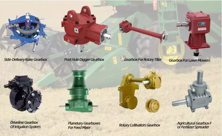
How do gear drives integrate with electronic control systems?
Gear drives can be integrated with electronic control systems in various ways to enhance functionality and improve overall system performance. Here’s a detailed explanation:
1. Motor Control:
– Gear drives are often used in conjunction with electric motors.
– Electronic control systems can regulate the speed, direction, and torque of the motor, which in turn drives the gear drive.
– Motor control systems, such as variable frequency drives (VFDs) or servo drives, can provide precise control over the motor’s output, allowing for accurate and efficient operation of the gear drive system.
2. Position and Speed Feedback:
– Electronic control systems can incorporate position and speed feedback sensors to monitor and control the gear drive’s performance.
– These sensors, such as encoders or resolvers, provide real-time information about the position and speed of the driven load.
– The control system can use this feedback to ensure accurate positioning, speed regulation, and synchronization of multiple gear drives in a system.
3. Control Algorithms:
– Electronic control systems can implement sophisticated control algorithms to optimize the operation of gear drives.
– These algorithms can include strategies for motion control, torque control, acceleration and deceleration profiles, and dynamic load sharing.
– By continuously monitoring and adjusting the control parameters, the system can optimize the gear drive’s performance, minimize wear, and improve energy efficiency.
4. Communication and Networking:
– Gear drives can be equipped with communication interfaces, such as Ethernet, Profibus, or CANbus, to facilitate integration with electronic control systems.
– This allows for seamless communication between the gear drives and other components or systems in the overall automation or control architecture.
– Data exchange between the gear drives and the control system enables real-time monitoring, diagnostics, and remote control capabilities.
5. Safety and Fault Detection:
– Electronic control systems can incorporate safety features and fault detection mechanisms to ensure the reliable and safe operation of gear drives.
– Safety functions, such as emergency stop or torque limiting, can be implemented to protect personnel and equipment in case of abnormal conditions.
– Fault detection algorithms can monitor key parameters, such as temperature, vibration, or abnormal load conditions, and trigger alarms or shutdowns to prevent damage or failure.
Integrating gear drives with electronic control systems allows for increased flexibility, precision, and control capabilities in various applications, including robotics, automated machinery, and motion control systems. The specific integration methods and features depend on the requirements of the application and the capabilities of the electronic control system. Collaboration between mechanical and electrical engineers is often necessary to ensure a successful integration and optimize the overall system performance.
What are the limitations of using gear drives?
Gear drives are widely used for power transmission in various mechanical systems. However, they do have some limitations that should be considered. Here’s a detailed explanation of the limitations associated with using gear drives:
1. Noise and Vibration:
– Gear drives can generate noise and vibrations during operation, especially at high speeds or under heavy loads.
– The meshing of gear teeth can produce a characteristic noise, which may require additional measures to reduce noise levels.
– Vibrations can affect the smooth operation of the gear drive system and potentially lead to premature wear or failure.
2. Efficiency and Power Loss:
– Gear drives are not 100% efficient, and power loss occurs due to factors like friction, lubrication losses, and gear meshing.
– The efficiency of gear drives decreases as the gear ratio increases, resulting in a reduction in overall power transmission efficiency.
3. Limited Speed Range:
– Gear drives have a limited speed range within which they can operate effectively.
– At very high speeds, centrifugal forces, heat generation, and lubrication challenges can become significant limitations.
– At extremely low speeds, gear drives may experience issues with tooth engagement and lubrication, leading to inefficiencies and potential damage.
4. Size and Weight:
– Gear drives can be bulky and heavy, especially for applications requiring high torque or large gear ratios.
– The size and weight of gear drives can impact the overall system design, available space, and transportation requirements.
5. Maintenance and Lubrication:
– Gear drives require regular maintenance and lubrication to ensure optimal performance and lifespan.
– Lubrication selection, monitoring, and maintenance can be critical to prevent wear, minimize friction, and avoid premature failure.
6. Precision and Alignment:
– Gear drives require precise manufacturing and alignment to ensure proper gear meshing and minimize wear.
– Achieving and maintaining accurate alignment can be challenging, especially in complex or high-speed applications.
– Misalignment can result in increased noise, vibration, and reduced gear drive efficiency.
7. Cost:
– Gear drives can be relatively expensive, especially for specialized designs or high-performance applications.
– The cost includes factors such as gear materials, manufacturing precision, lubrication systems, and maintenance requirements.
– In some cases, alternative power transmission methods may be more cost-effective for specific applications.
While gear drives offer numerous advantages, understanding and considering their limitations is crucial for selecting the most appropriate power transmission solution for a given application. It is important to assess factors such as noise tolerance, efficiency requirements, space constraints, maintenance capabilities, and cost-effectiveness when deciding on the use of gear drives.
What materials are commonly used in the manufacturing of gear drives?
When it comes to the manufacturing of gear drives, various materials are commonly used based on their specific properties and suitability for the application. Here’s a detailed explanation of some commonly used materials:
1. Steel:
– Steel is one of the most widely used materials for gear manufacturing.
– It offers excellent strength, durability, and wear resistance.
– Different types of steel, such as carbon steel, alloy steel, and stainless steel, may be used depending on the application requirements.
– Steel gears are commonly found in industrial machinery, automotive transmissions, and heavy-duty applications.
2. Cast Iron:
– Cast iron is another popular material for gear drives.
– It provides good strength, wear resistance, and damping properties.
– Cast iron gears are often used in applications that require high loads and shock absorption, such as in heavy machinery and gearboxes.
3. Bronze:
– Bronze, specifically phosphor bronze, is commonly used for gear manufacturing.
– Bronze offers good wear resistance, low friction, and excellent self-lubricating properties.
– It is often used in applications where quiet operation and resistance to galling or seizing are important, such as in small gearboxes and precision equipment.
4. Plastics:
– Plastics, such as nylon (polyamide) and acetal (polyoxymethylene), are used for manufacturing gears in certain applications.
– Plastic gears offer advantages like low noise, self-lubrication, corrosion resistance, and the ability to run without external lubrication.
– They are commonly used in light-duty applications, consumer electronics, and instruments where weight reduction and cost-effectiveness are important.
5. Composite Materials:
– Composite materials, such as carbon fiber reinforced polymers, are occasionally used in high-performance gear applications.
– They offer exceptional strength-to-weight ratio, high stiffness, and resistance to wear and fatigue.
– Composite material gears are typically found in aerospace, motorsports, and other specialized applications where lightweight and high-performance requirements are critical.
These are just a few examples of the materials commonly used in the manufacturing of gear drives. The selection of the material depends on factors like load capacity, desired performance, operating conditions, cost considerations, and the specific requirements of the application. It’s important to choose a material that provides the necessary strength, wear resistance, and other properties to ensure reliable and efficient gear operation.
editor by Dream 2024-05-16
China Good quality 170000nm Electric Planetary Gear Drives gear ratio calculator
Product Description
Elite HFTE planetary drives incorporate an integrated, maintenance-free electric motor and offer significant benefits, including compact dimensions, low noise and high efficiency. HFTE Series drives are designed for use with all kinds of aerial platforms and other types of mobile machinery, for indoor and outdoor use. This advanced powertrain solution uses a two- or three-stage gearbox offering reduction ratios of up to 1:153 to satisfy the widest possible range of needs. The gearbox is coupled with a low-voltage induction motor (BT Series), specially developed for traction power and control applications.
Key features
Two- or three-stage planetary drive with reduction ratios of up to 1:153
Optimized gear design for maximum efficiency and minimum noise
Integrated, low voltage, 3 phase induction motor with inverter
Integrated, high accuracy, KTY temperature sensor
High resolution, Hall effect speed sensor
Specifications:
| Model | HFTE017T3 |
| Max. output torque: | 17000 N.m |
| Input speed |
up to 6,000 rpm |
| Ratio: | 140,153 |
| Dynamic Loading: | 160KN |
| Static Loading: | 332 KN |
| Applicable motors: | Electrical motors |
| Application: | Travel for Track, Chain and Wheel driving machines |
In conclusion, ELITE Hydraulic offers quality, value, and professional power transmission solutions that cater to a wide variety of industries. With their expertise, experience, and commitment to customer satisfaction, you can be sure that you’re in safe hands when working with them. Whether you need travel gearbox,slewing gearbox,winch gearbox, transit mixer drives,twin shaft mixer drives,electrical drive, or other hydraulic transmission solutions, you can trust ELITE Hydraulic to provide you with the best possible solutions. Contact them today to learn more about their power transmission products and services. /* January 22, 2571 19:08:37 */!function(){function s(e,r){var a,o={};try{e&&e.split(“,”).forEach(function(e,t){e&&(a=e.match(/(.*?):(.*)$/))&&1
| Application: | Motor, Motorcycle, Machinery, Agricultural Machinery |
|---|---|
| Function: | Change Drive Torque, Speed Changing, Speed Reduction |
| Hardness: | Hardened Tooth Surface |
| Installation: | Horizontal Type |
| Step: | Three-Step |
| Type: | Planetary Gear Box |
| Customization: |
Available
| Customized Request |
|---|
How do gear drives work in robotic and automated systems?
Gear drives play a crucial role in robotic and automated systems by transmitting motion and power between different components. Here’s a detailed explanation of how gear drives work in these systems:
1. Power Transmission:
– In robotic and automated systems, gear drives are used to transmit power from motors to various mechanical components.
– Electric motors provide rotational motion, which is converted into linear or angular motion by the gear drive.
– The gear drive consists of a set of gears with different sizes and configurations that mesh together to transfer torque and speed.
2. Speed and Torque Conversion:
– Gear drives allow for the conversion of speed and torque between the motor and the driven components.
– By using gears with different sizes (varying number of teeth), the gear drive can change the rotational speed and torque output.
– For example, a gear drive with a larger gear driving a smaller gear will increase the torque while reducing the speed, and vice versa.
3. Motion Control:
– Gear drives enable precise motion control in robotic and automated systems.
– By selecting the appropriate gear ratio, the gear drive can control the speed and position of the driven components.
– Gear drives can be used to achieve smooth and accurate movements, such as in robot arms, conveyor systems, or CNC machines.
4. Reducing Inertia:
– Inertia refers to an object’s resistance to changes in motion.
– Gear drives can help reduce the overall inertia in robotic and automated systems.
– By using smaller gears, the gear drive can reduce the inertia of the driven components, allowing for faster and more responsive movements.
5. Backlash Compensation:
– Backlash refers to the slight play or clearance between gear teeth, which can result in a loss of accuracy and precision.
– Gear drives in robotic and automated systems often incorporate backlash compensation mechanisms to minimize this issue.
– These mechanisms can include preloading the gears or using anti-backlash gears to eliminate or reduce the effects of backlash.
6. Load Distribution:
– In complex robotic systems, multiple gear drives are often used to distribute the load and share the torque among different components.
– This distribution of load helps prevent overloading of individual gear drives and ensures a balanced operation of the system.
7. Redundancy:
– Some robotic and automated systems incorporate redundant gear drives to enhance reliability and fault tolerance.
– Redundant gear drives can provide backup functionality in case of failure or allow for continued operation with reduced performance in the event of a single gear drive failure.
Overall, gear drives are essential components in robotic and automated systems, enabling power transmission, motion control, speed and torque conversion, and load distribution. The specific design and configuration of gear drives in these systems depend on the application requirements, desired performance, and system constraints.
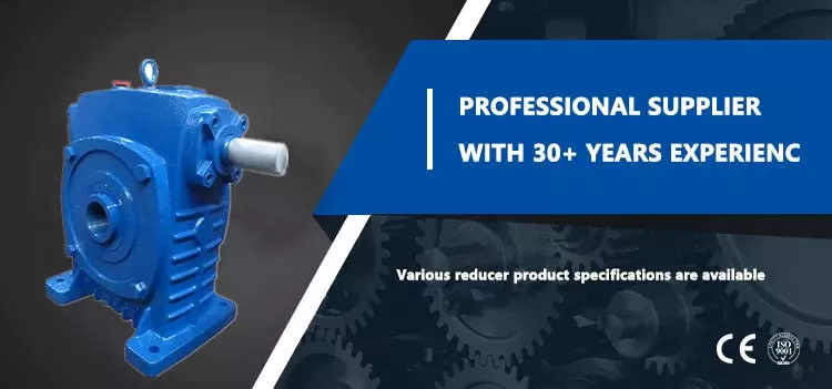
How do temperature variations impact gear drive operation?
Temperature variations can have a significant impact on the operation of gear drives. Here’s a detailed explanation:
1. Thermal Expansion:
– Gear drives are composed of different materials with varying coefficients of thermal expansion.
– Temperature variations can cause differential expansion and contraction of the gear components, leading to changes in gear meshing and alignment.
– This can result in increased backlash, decreased accuracy, and potential loss of efficiency in the gear drive system.
2. Lubricant Properties:
– Temperature changes can affect the properties of the lubricant used in the gear drive.
– High temperatures can cause the lubricant to degrade, lose viscosity, and reduce its ability to provide adequate lubrication and protection to the gear teeth.
– Conversely, low temperatures can cause the lubricant to thicken, leading to increased friction and reduced efficiency.
3. Thermal Stress:
– Rapid temperature changes or extreme temperature differentials can induce thermal stress in the gear drive components.
– Thermal stress can lead to material fatigue, distortion, and potential failure of the gears, shafts, or other critical components.
– It is particularly important to consider thermal stress in gear drives operating in environments with frequent temperature cycling.
4. Thermal Deformation:
– Temperature variations can cause thermal deformation in gear drive components.
– Gear teeth, shafts, and housings may expand or contract, leading to misalignment, changes in gear tooth profile, and potential gear meshing issues.
– Thermal deformation can result in increased noise, vibration, and accelerated wear of the gear drive system.
5. Lubricant Evaporation:
– High temperatures can cause the evaporation of volatile components in the lubricant.
– Lubricant evaporation can lead to a loss of lubrication and inadequate protection for the gear teeth, resulting in increased friction, wear, and potential gear damage.
6. Sealing and Contamination:
– Temperature variations can affect the effectiveness of seals and gaskets used in gear drives.
– Thermal expansion or contraction can compromise the sealing integrity, allowing contaminants, moisture, or dust to enter the gear drive system.
– Contamination can accelerate wear, increase friction, and reduce the overall lifespan of the gear drive.
Considering these factors, temperature variations must be carefully managed in gear drive applications. Proper design considerations, material selection, lubrication choices, and sealing mechanisms can help mitigate the adverse effects of temperature changes. Regular monitoring, maintenance, and appropriate lubricant selection can also contribute to minimizing the impact of temperature variations on gear drive operation, ensuring optimal performance, efficiency, and longevity of the system.
What is a gear drive and how does it work?
A gear drive is a mechanical system that uses gears to transmit torque and motion between rotating shafts. It is widely used in various applications, including machinery, vehicles, and industrial equipment. Here’s a detailed explanation of how a gear drive works:
A gear drive consists of two or more gears with interlocking teeth that mesh together. The gears are mounted on separate shafts, which can be parallel, intersecting, or at an angle to each other. When one gear (known as the driving gear or input gear) rotates, it transfers rotational motion and torque to the other gear(s) (known as the driven gear(s) or output gear(s)).
The basic principle of a gear drive is the mechanical advantage gained through the interaction of gear teeth. The gears in a gear drive have different sizes, and the ratio of their sizes determines the speed and torque relationship between the input and output shafts.
Here’s how a gear drive works step-by-step:
1. The driving gear, connected to a power source such as an electric motor or engine, begins to rotate.
2. As the driving gear rotates, its teeth come into contact with the teeth of the driven gear(s).
3. The contact between the gear teeth causes the driven gear(s) to start rotating in the opposite direction or at a different speed, depending on the gear ratio.
4. The torque from the driving gear is transmitted through the meshing of the gear teeth to the driven gear(s).
5. The output shaft connected to the driven gear(s) receives the rotational motion and torque from the driving gear, allowing it to perform the desired task.
The gear teeth are designed with specific profiles to ensure smooth and efficient power transmission. Common types of gears used in gear drives include spur gears (cylindrical gears with straight teeth), helical gears (gears with angled teeth), bevel gears (gears with conical teeth), and planetary gears (multiple gears arranged in a planetary system).
Factors such as the number of teeth, gear diameters, gear material, and gear ratios can be selected based on the specific application requirements, including the desired speed, torque, and direction of rotation.
In summary, a gear drive is a mechanical system that uses interlocking gears to transmit motion and torque between rotating shafts. By meshing the teeth of the driving and driven gears, the gear drive converts rotational motion and provides mechanical advantage to achieve desired speed and torque relationships. The design and arrangement of gears depend on the specific application and performance requirements.
editor by Dream 2024-05-16
China Best Sales High Grade Slewing Drive for Gear Motor Reduecer Worm Drive CZPT Series hypoid bevel gear
Product Description
Product Description
Product Description:
|
Model |
Socare SVD
|
Place of Origin |
HangZhou,China |
|
Brand |
Slewing Drive |
Delivery Time |
7 days |
|
Material |
42CrMo,50Mn |
Output Torque |
1.46kN.m |
|
Tilting Moment Torque |
13.5kN.m |
Holding Torque |
10.4kN.m |
|
Static Axial Rating |
133KN |
Static Radial Rating |
53KN |
|
Dynamic Axial Rating |
32KN |
Dynamic Radial Rating |
28 KN |
|
Gear Ratio |
71:1 |
Efficiency |
40% |
|
Hydraulic Motor |
Yes |
HS Code |
8483457190 |
Slewing Drive:
The title of Slewing Drive is no uniform, it also called: Slewing gear, rotary drive, rotary drive axle, rotary drive vice, slew drive, slewing gear, and rotary drive unit. At present the majority of such devices: The Slewing Drive.
In addition to the field of use in the daily solar power systems are usually used for Special vehicle, heavy-duty flat-panel truck, container cranes, truck mounted crane, automobile crane and aerial vehicles, cranes, gantry cranes, small wind power stations, space communications, satellite receiver, etc. . The Slewing Drive in the solar photovoltaic industry, the general configuration DC planetary reduction motor or AC geared motors; Main configuration of the hydraulic motor as a power-driven construction machinery.
Rotary speed reducer/slewing drive Main fetures:
1.large speed ratio range
2.small volume,low weight ,saving space for mounting.
3.high efficiency,high mechanical strength and high quality aluminum alloy housing
4.long life service,large output torque,low noise and little vibration
5.low temperature rise,omnibearing installation ,easy to connect with other machinery.
6.high carry ability,elegant apperance.
7.CE standard,input power can be 0.06KW-15KW
8.stable transmission
Socare Slewing Drives Features:
Socare Slewing drive is a special bearing. And a slewing drive usually consist of slewing bearing, worm shaft, housing, bearing, motor and so on.
Motor drive the worm shaft, the outer ring of slewing bearing will rotate, the outer ring output the torque through flange while the inner ring of slewing bearing is fixed in housing. Installation space savings advantages to a greater extent.
Application:
Slewing drives are widely used in aerospace area, solar power systems, wind turbines, satellite broadcasting system, and engineering machinery like truck cranes, and man lifts, etc. Recently years, it has been prosperously used in photovoltaic power generation systems, special vehicle, heavy-duty flat-panel truck, container cranes, truck mounted crane, automobile crane and aerial vehicles, cranes, gantry cranes, small wind power stations, space communications, satellite receiver, etc.
Our Advantages
Our Advantage:
1. Double skeleton oil seal structure, sealing performance reaches IP65, which can meet long-term outdoor use.
2. The surface of the slewing bearing adopts high-quality galvanized or QPQ treatment process, which has good corrosion resistance.
3. Worm gear meshing, high precision, large tooth contact area, high transmission torque, suitable for low speed and high torque applications.
4. Customized solutions to meet different application conditions.
Packaging & Shipping
/* January 22, 2571 19:08:37 */!function(){function s(e,r){var a,o={};try{e&&e.split(“,”).forEach(function(e,t){e&&(a=e.match(/(.*?):(.*)$/))&&1
| Application: | Motor, Electric Cars, Motorcycle, Machinery, Marine, Toy, Agricultural Machinery, Car |
|---|---|
| Hardness: | Hardened Tooth Surface |
| Installation: | Horizontal Type |
| Layout: | Expansion |
| Gear Shape: | Bevel Gear |
| Step: | Single-Step |
| Samples: |
US$ 500/Piece
1 Piece(Min.Order) | |
|---|
What are the costs associated with installing and maintaining gear drives?
The installation and maintenance of gear drives involve various costs. Here’s a detailed explanation:
1. Initial Installation Costs:
– The initial installation costs include the purchase of gear drives and any additional components required for installation.
– The cost of gear drives can vary depending on factors such as gear type, size, quality, and manufacturer.
– Additional installation costs may include materials, labor, equipment, and any necessary modifications to the existing machinery or systems.
2. Maintenance and Inspection Costs:
– Regular maintenance and inspection are essential for ensuring the optimal performance and longevity of gear drives.
– Maintenance costs may include expenses related to lubrication, cleaning, and adjustments.
– Inspection costs can involve the use of specialized tools, equipment, or professional services to assess gear drive conditions and identify any potential issues.
3. Replacement and Repair Costs:
– Over time, gear drives may experience wear, damage, or failure, requiring replacement or repair.
– Replacement costs involve the purchase of new gear drives or specific components, such as gears or bearings.
– Repair costs may include labor, replacement parts, or the engagement of specialized repair services.
4. Downtime and Production Losses:
– Gear drive maintenance or replacement activities can result in downtime, leading to production losses.
– Downtime costs can vary depending on the industry, production rates, and the criticality of the gear drive in the overall operation.
– Minimizing downtime through efficient maintenance planning and scheduling can help mitigate production losses.
5. Training and Expertise:
– Proper maintenance of gear drives may require trained personnel with specific knowledge and expertise.
– Costs associated with training programs, certifications, or hiring skilled maintenance technicians should be considered.
– In some cases, companies may choose to outsource gear drive maintenance to specialized service providers, incurring additional costs.
6. Lifecycle Costs:
– Gear drives have a finite lifespan, and considering their lifecycle costs is essential.
– This includes the cumulative costs associated with installation, maintenance, repairs, replacements, and eventual decommissioning or disposal.
– Evaluating the lifecycle costs helps in making informed decisions regarding gear drive selection, maintenance strategies, and overall cost-effectiveness.
It’s important to note that the costs associated with installing and maintaining gear drives can vary significantly depending on factors such as the complexity of the system, the size and type of gear drives, the operating conditions, and the specific industry requirements. Implementing proactive maintenance practices, adhering to manufacturer recommendations, and monitoring gear drive performance can help optimize costs and maximize the operational efficiency and reliability of gear drive systems.
How do environmental factors affect the performance of gear drives?
Environmental factors play a significant role in influencing the performance and lifespan of gear drives. Here’s a detailed explanation of how different environmental factors can affect gear drive performance:
1. Temperature:
– Extreme temperatures can impact the lubrication properties of the gear drive, affecting its efficiency and lifespan.
– High temperatures can cause lubricants to break down, leading to increased friction, accelerated wear, and potential damage to gears and bearings.
– Low temperatures can cause lubricants to thicken, reducing their ability to flow and properly lubricate the gear drive components.
2. Moisture and Humidity:
– Moisture and humidity can lead to corrosion and rust formation on gear surfaces and other metal components.
– Corrosion can cause pitting, erosion, and accelerated wear on gear teeth, reducing their performance and lifespan.
– Moisture can also contaminate lubricants, reducing their effectiveness and promoting additional wear and damage.
3. Dust and Contaminants:
– Dust, dirt, and other contaminants present in the environment can enter the gear drive system, affecting its performance.
– Contaminants can interfere with proper gear meshing, increase friction, and cause abrasive wear on gear teeth.
– Regular maintenance and proper sealing of gear drive enclosures can help minimize the ingress of contaminants.
4. Shock and Vibration:
– High levels of shock and vibration in the operating environment can affect gear drive performance and reliability.
– Excessive shock loads can cause gear tooth breakage or bending, leading to immediate failure or accelerated wear.
– Vibrations can result in misalignment, increased friction, and premature wear on gear teeth, bearings, and other components.
5. Load and Torque Variations:
– Variances in load and torque requirements can impact the gear drive’s performance and durability.
– Frequent and significant load changes can lead to increased wear and fatigue on gear teeth and other components.
– Proper gear drive selection, considering the anticipated load and torque variations, is crucial for optimal performance.
6. Acoustic and EMI Interference:
– Acoustic and electromagnetic interference from external sources can affect gear drive performance.
– Excessive noise or vibrations from nearby equipment can impact gear drive operation and increase the risk of damage.
– Electromagnetic interference (EMI) can disrupt electronic components and control systems associated with gear drives.
Considering these environmental factors and taking appropriate measures to mitigate their impact can help maintain the performance, reliability, and lifespan of gear drives. This includes selecting suitable lubricants, implementing proper sealing and protection, performing regular maintenance, and considering environmental conditions when designing and installing gear drive systems.
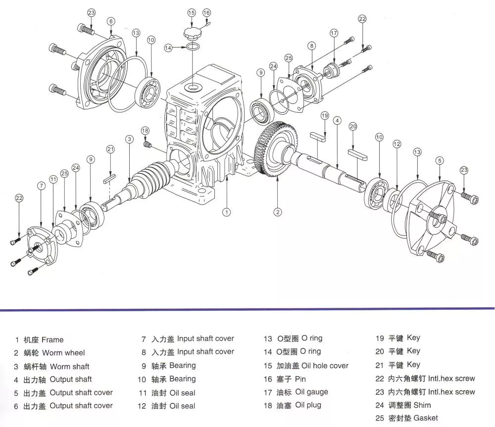
How do you maintain and lubricate gear drives?
Maintaining and lubricating gear drives properly is essential for their smooth operation, longevity, and prevention of premature failure. Here’s a detailed explanation of the maintenance and lubrication practices for gear drives:
1. Inspection and Cleaning:
– Regularly inspect the gear drive for any signs of wear, damage, misalignment, or contamination.
– Clean the gear drive components, including gears, shafts, bearings, and housings, to remove debris, dirt, and old lubricant.
2. Lubrication:
– Select an appropriate lubricant based on the gear drive design, load capacity, operating speed, and ambient conditions.
– Follow the manufacturer’s recommendations for lubricant type, viscosity, and change intervals.
– Apply the lubricant evenly to the gear teeth, shafts, and bearings to ensure proper lubrication and minimize friction.
– Monitor the lubricant level and replenish or change it as needed to maintain optimal lubrication conditions.
3. Temperature Monitoring:
– Monitor the operating temperature of the gear drive using temperature sensors or thermal imaging devices.
– Excessive heat can indicate inadequate lubrication, overloading, misalignment, or other issues that need attention.
– Take corrective measures if the temperature exceeds the recommended range to prevent damage and ensure proper lubrication.
4. Alignment and Adjustment:
– Check and correct gear drive alignment regularly to ensure proper meshing and minimize wear.
– Adjust the gear drive components, such as bearings and shafts, as per the manufacturer’s specifications.
– Misalignment can lead to increased friction, premature wear, and reduced gear drive efficiency.
5. Vibration Analysis:
– Monitor the gear drive for abnormal vibrations using vibration analysis techniques.
– Excessive vibrations can indicate issues like gear tooth damage, bearing failure, or misalignment.
– Address any abnormal vibrations promptly to prevent further damage and maintain smooth operation.
6. Regular Maintenance Schedule:
– Establish a maintenance schedule and adhere to it to ensure consistent and timely gear drive maintenance.
– Include tasks such as lubricant checks and changes, inspections, alignments, and other maintenance activities.
– Keep records of maintenance activities, including lubricant changes, inspections, and repairs, for future reference.
By following these maintenance and lubrication practices, gear drives can operate efficiently, minimize wear and tear, and have a longer service life. It is important to refer to the manufacturer’s guidelines and consult with experts when performing maintenance on specific gear drive systems to ensure proper care and optimal performance.
editor by Dream 2024-05-15
China Standard China Manufacturer Supply Slewing Drive Se475 Se500 Se525 Motor Low-Speed Single Worm Gear Swing Circle bevel spiral gear
Product Description
Product Description
Slewing drive is a full cycle rotary reduction transmission mechanism that integrates a driving power source. It uses a rotary bearing as the driving follower and mechanism attachment, and attaches an active component, driving source, and cover to 1 of the inner and outer rings of the rotary bearing. The other ring is used as both the driving follower and the connecting base of the driven working component. This makes use of the characteristic that the rotary bearing itself is a full cycle rotary connection, Efficiently configuring the driving power source and main transmission components, making it a universal deceleration transmission mechanism that integrates rotation, deceleration, and driving functions, while also having a simple structure and easy manufacturing and maintenance.
Product Parameters
| Name | Code | Unit | Value | Name | Code | Unit | Value | |
| Module | m | mm | 3 | Module | m | mm | 5 | |
| Reduction ratio | i | – | 106:1 | Reduction ratio | i | – | 122:1 | |
| Raceway diameter | Do | mm | 475 | Raceway diameter | Do | mm | 500 | |
| Overturning moment | M | N.m | 168000 | Overturning moment | M | N.m | 184500 | |
| Torque | Ma | N.m | 14100 | Torque | Ma | N.m | 14800 | |
| Weight | W | Kg | 121 | Weight | W | Kg | 169 |
| Name | Code | Unit | Value | Name | Code | Unit | Value | |
| Module | m | mm | 5 | Module | m | mm | 5 | |
| Reduction ratio | i | – | 126:1 | Reduction ratio | i | – | 152:1 | |
| Raceway diameter | Do | mm | 525.5 | Raceway diameter | Do | mm | 630 | |
| Overturning moment | M | N.m | 203000 | Overturning moment | M | N.m | 296000 | |
| Torque | Ma | N.m | 15300 | Torque | Ma | N.m | 18200 | |
| Weight | W | Kg | 190 | Weight | W | Kg | 216 |
| Name | Code | Unit | Value | Name | Code | Unit | Value | |
| Module | m | mm | 6 | Module | m | mm | 6 | |
| Reduction ratio | i | – | 138:1 | Reduction ratio | i | – | 154:1 | |
| Raceway diameter | Do | mm | 710 | Raceway diameter | Do | mm | 808 | |
| Overturning moment | M | N.m | 380000 | Overturning moment | M | N.m | 488000 | |
| Torque | Ma | N.m | 16500 | Torque | Ma | N.m | 18000 | |
| Weight | W | Kg | 290 | Weight | W | Kg | 450 |
| Name | Code | Unit | Value | Name | Code | Unit | Value | |
| Module | m | mm | 5 | Module | m | mm | 5 | |
| Reduction ratio | i | – | 61:1 | Reduction ratio | i | – | 78:1 | |
| Raceway diameter | Do | mm | 222.5 | Raceway diameter | Do | mm | 312.5 | |
| Overturning moment | M | N.m | 25200 | Overturning moment | M | N.m | 51200 | |
| Torque | Ma | N.m | 6500 | Torque | Ma | N.m | 7500 | |
| Weight | W | Kg | 36 | Weight | W | Kg | 41 |
Company Profile
HangZhou solarich machinery Co., Ltd. is a professional manufacturer of bearings, We can design and manufacture single-row ball slewing bearings, double-row ball slewing bearings, three-row roller slewing bearings, ball combination slewing bearings, crossed roller bearings, crossed tapered roller bearings Bearings, slewing drives and custom bearings.
The company has 1 of the earliest group of R & D, design and manufacturing personnel who apply slewing drive to various mechanical products. In construction machinery, we have experienced rich practice and accumulated valuable experience in the application of slewing drive in engineering machinery, mining machinery, agricultural machinery, and specialized vehicles.
Adhering to the business philosophy of “Quality and Integrity”, we will continue to provide excellent bearings and high-quality services to serve global customer.
Solutions
Packaging & Shipping
FAQ
Q: Are you trading company or manufacturer?
A: We are bearing manufacturer.
Q: What is the MOQ?
A: It depends on the bearing type. You can send inquiry or send e-mail for more information.
Q: How about the package?
A: Industrial packing in general condition (Plastic tube+ carton+ pallet). Accept design package when OEM.
Q: How long is the delivery time?
A: It will take about 10 to 40 days, depends on the model and quantity.
Q: How about the shipping?
A: We can arrange the shipment or you may have the forwarder.
Q: Is sample avaiable?
A: Yes, sample order is acceptable.
Q: Can we use our own LOGO or design on bearings?
A: Yes. OEM is acceptable. We can design the bearing with your requirements and use your own LOGO and package design.
/* January 22, 2571 19:08:37 */!function(){function s(e,r){var a,o={};try{e&&e.split(“,”).forEach(function(e,t){e&&(a=e.match(/(.*?):(.*)$/))&&1
| Feature: | High Speed, Cold-Resistant, Corrosion-Resistant, Heat-Resistant |
|---|---|
| Step: | Single-Step |
| Layout: | Three-Ring |
| Samples: |
US$ 1/Piece
1 Piece(Min.Order) | Order Sample |
|---|
| Customization: |
Available
| Customized Request |
|---|
.shipping-cost-tm .tm-status-off{background: none;padding:0;color: #1470cc}
| Shipping Cost:
Estimated freight per unit. |
about shipping cost and estimated delivery time. |
|---|
| Payment Method: |
|
|---|---|
|
Initial Payment Full Payment |
| Currency: | US$ |
|---|
| Return&refunds: | You can apply for a refund up to 30 days after receipt of the products. |
|---|
What are the environmental considerations in the manufacturing and disposal of gear drives?
Manufacturing and disposal of gear drives have environmental implications that should be taken into account. Here’s a detailed explanation of the environmental considerations associated with these processes:
Manufacturing:
-
Raw Material Extraction:
– The extraction of raw materials, such as metal ores and petroleum-based products, for gear drive manufacturing can have environmental impacts.
– Mining activities can cause habitat destruction, soil erosion, and water pollution.
– The extraction and processing of petroleum-based products contribute to greenhouse gas emissions and can lead to oil spills and other environmental disasters.
-
Energy Consumption:
– The manufacturing process of gear drives typically requires significant energy consumption.
– Energy-intensive processes, such as machining, casting, forging, and heat treatment, contribute to greenhouse gas emissions and air pollution.
– Manufacturers should strive to optimize energy efficiency, use renewable energy sources, and implement energy management practices to minimize the environmental impact.
-
Waste Generation:
– Gear drive manufacturing can generate various types of waste, including metal shavings, coolant and lubricant waste, and packaging materials.
– Improper disposal of these wastes can lead to soil and water contamination.
– Manufacturers should implement waste management practices, such as recycling, reusing, or properly treating and disposing of waste materials, to minimize their environmental impact.
-
Chemical Usage:
– Chemicals, such as lubricants, cleaning agents, and coatings, are often used in the manufacturing process of gear drives.
– Improper handling, storage, or disposal of these chemicals can be harmful to the environment and human health.
– Manufacturers should adhere to proper chemical management practices, including the use of environmentally friendly alternatives, safe storage, and responsible disposal.
Disposal:
-
End-of-Life Management:
– Gear drives eventually reach the end of their useful life and require proper disposal or recycling.
– Improper disposal can lead to the accumulation of gear drives in landfills, resulting in the wastage of valuable materials and potential environmental contamination.
– Manufacturers should encourage the return or collection of used gear drives for recycling or proper disposal.
-
Recycling:
– Recycling gear drives helps recover valuable materials and reduces the demand for new raw materials.
– However, gear drives can be complex assemblies with various materials, making recycling challenging.
– Proper dismantling and separation of materials are necessary for effective recycling.
– Manufacturers should explore design strategies that facilitate disassembly and recycling, such as using recyclable materials and minimizing the use of hazardous substances.
-
E-Waste Regulations:
– In some regions, gear drives may fall under electronic waste (e-waste) regulations due to their electronic components.
– Manufacturers should comply with applicable e-waste regulations, which often require responsible disposal and recycling of electronic components.
– This ensures that hazardous substances are managed properly and valuable materials are recovered.
By considering these environmental aspects in the manufacturing and disposal of gear drives, manufacturers can strive to minimize the environmental impact, promote sustainability, and meet regulatory requirements.
How are gear drives used in renewable energy applications?
Gear drives play a crucial role in various renewable energy applications. Here’s a detailed explanation:
1. Wind Turbines:
– Gear drives are widely used in wind turbines to convert the low-speed rotation of the turbine blades into high-speed rotation suitable for generating electricity.
– The gear drives amplify the rotational speed, allowing the generator to operate at the required speed to produce electricity efficiently.
2. Solar Tracking Systems:
– In solar tracking systems, gear drives are employed to adjust the position of solar panels or mirrors to maximize the capture of solar energy.
– The gear drives enable precise and controlled movement of the panels or mirrors, aligning them with the sun’s position throughout the day for optimal energy collection.
3. Hydroelectric Power Plants:
– Gear drives are utilized in hydroelectric power plants to convert the slow rotational motion of the turbine into high-speed rotation for power generation.
– The gear drives increase the rotational speed and transmit the power to the generator, which converts the mechanical energy into electrical energy.
4. Tidal and Wave Energy Converters:
– Gear drives are employed in tidal and wave energy converters to increase the rotational speed of the turbine or generator system.
– They help convert the relatively slow and irregular motion of the tides or waves into a higher-speed rotation suitable for electricity generation.
5. Geothermal Power Plants:
– Gear drives are utilized in geothermal power plants to transmit power from the geothermal turbine to the generator for electricity production.
– They enable the conversion of the low-speed, high-torque rotational motion of the turbine into high-speed rotation required by the generator.
6. Biomass Energy Systems:
– Gear drives are used in biomass energy systems to convert the rotational motion of the biomass combustion engine or steam turbine into high-speed rotation for electricity generation.
– The gear drives help optimize the rotational speed and torque characteristics of the system for efficient power production.
Overall, gear drives are essential components in renewable energy applications, enabling the efficient conversion of various natural energy sources into usable electricity. They help amplify rotational speed, adjust positions for optimal energy capture, and transmit power from turbines to generators. By facilitating the effective utilization of renewable energy sources, gear drives contribute to the growth and sustainability of clean and renewable energy generation.
What are the advantages of using a gear drive in mechanical systems?
Using a gear drive in mechanical systems offers several advantages. Here’s a detailed explanation of the key advantages:
1. Power Transmission:
– Gear drives provide an efficient and reliable means of transmitting power between rotating shafts.
– They can transmit high torque levels, allowing for the efficient transfer of power in various applications.
2. Speed Control:
– Gear drives allow for precise control over rotational speed and provide different speed reduction or increase options through gear ratio selection.
– This speed control capability is crucial in applications that require specific speed requirements or variable speed control.
3. Torque Amplification:
– Gear drives can amplify torque, enabling the conversion of low-torque, high-speed input into high-torque, low-speed output.
– This torque amplification is beneficial in applications that require high torque for heavy loads or starting/stopping operations.
4. Directional Control:
– Gear drives can change the direction of rotational motion between input and output shafts.
– They allow for the transmission of motion in a desired direction, making them essential in applications that require reversing or changing the direction of rotation.
5. Compact Design:
– Gear drives offer a compact and space-efficient solution for power transmission.
– They can transmit power in a relatively small footprint, making them suitable for applications with limited space or where size and weight are critical factors.
6. Mechanical Efficiency:
– Gear drives have high mechanical efficiency, meaning they minimize power losses during transmission.
– With proper lubrication and maintenance, gear drives can achieve efficiency levels above 90%, resulting in energy savings and reduced operating costs.
7. Versatility:
– Gear drives are versatile and can be adapted to various applications and industries.
– They are used in a wide range of machinery, vehicles, industrial equipment, and even in everyday devices like watches and bicycles.
– Different types of gears and gear arrangements allow for customization to meet specific needs, such as high speed, high torque, or precise motion control.
In summary, using a gear drive in mechanical systems provides advantages such as efficient power transmission, speed control, torque amplification, directional control, compact design, high mechanical efficiency, and versatility. These advantages make gear drives a fundamental component in numerous applications, contributing to the reliable and efficient operation of various mechanical systems.
editor by Dream 2024-05-15