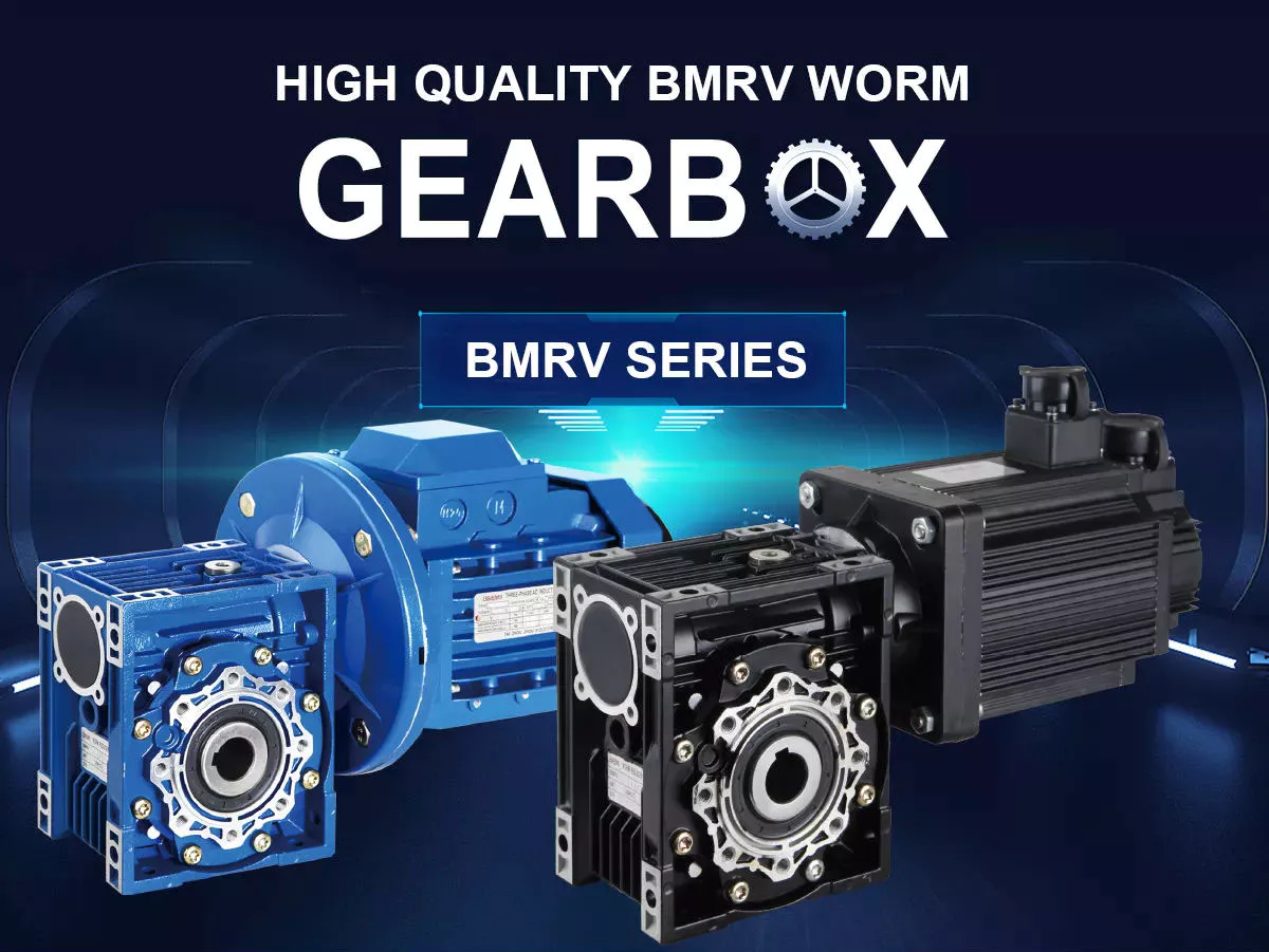
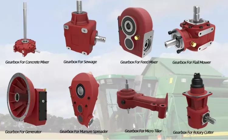
Product Description
Product Description
HMCG-I Series Harmonic Reducer
Introducing the HMCG-I Series Harmonic Reducer from HangZhou Yijiaang Automation Technology Co., Ltd! Designed for aerospace, robotics, semiconductors, power inspection, and automation equipment.
Experience the Power of Harmonic Gear Transmission
Discover the cutting-edge transmission mode invented by C.W. Musser in 1955. The HMCG-I series utilizes elastic deformation for movement and power transmission, replacing traditional rigid components with flexibility for enhanced functionality.
Unleash the Deceleration Principle
Harness the power of the deceleration principle with the HMCG-I series harmonic reducer. The flexwheel, rigid wheel, and wave generator work together seamlessly for precise and efficient movement transmission.
Product Specifications
Product Name:
Industrial Robot Ultra-Thin Series Hmcg Harmonic Precision Reducer
Applicable Industries: Machinery, Agricultural Machinery, Car, Robot
Hardened Tooth Surface: Yes
Installation Type: Horizontal Type
Upgrade to the future of precision and efficiency today with the HMCG-I series harmonic reducer!
Company Name: HangZhou Yijiaang Automation Technology Co., Ltd
Product Parameters
| Model | Reduction ratio | Rated torque at input 2000r/min |
Permissible CHINAMFG torque at start/stop | Permissible max.value of ave.load torque | instantaneous permissible max.torque | Permssibie max.input rotational speed | Permissible ave.input rotational speed | Backlash (arc sec) | Transmission accuracy(arc sec) |
| Nm | Nm | Nm | Nm | r/min | r/min | ≤ | ≤ | ||
| 14 | 50 | 7 | 23 | 9 | 46 | 8000 | 3500 | 20 | 90 |
| 80 | 10 | 30 | 14 | 51 | 20 | 90 | |||
| 100 | 10 | 36 | 14 | 70 | 10 | 90 | |||
| 17 | 50 | 21 | 44 | 34 | 91 | 7000 | 3500 | 20 | 90 |
| 80 | 29 | 56 | 35 | 113 | 20 | 90 | |||
| 100 | 31 | 70 | 51 | 143 | 10 | 90 | |||
| 20 | 50 | 33 | 73 | 44 | 127 | 6000 | 3500 | 20 | 60 |
| 80 | 44 | 96 | 61 | 165 | 20 | 60 | |||
| 100 | 52 | 107 | 64 | 191 | 10 | 60 | |||
| 120 | 52 | 113 | 64 | 161 | 10 | 60 | |||
| 25 | 50 | 51 | 127 | 72 | 242 | 5500 | 3500 | 20 | 60 |
| 80 | 82 | 178 | 113 | 332 | 20 | 60 | |||
| 100 | 87 | 204 | 140 | 369 | 10 | 60 | |||
| 120 | 87 | 217 | 140 | 395 | 10 | 60 | |||
| 32 | 50 | 99 | 281 | 140 | 497 | 4500 | 3500 | 20 | 60 |
| 80 | 153 | 395 | 217 | 738 | 10 | 60 | |||
| 100 | 178 | 433 | 281 | 841 | 10 | 60 | |||
| 120 | 178 | 459 | 281 | 892 | 10 | 60 | |||
| 40 | 50 | 178 | 523 | 255 | 892 | 4000 | 3000 | 10 | 60 |
| 80 | 268 | 675 | 369 | 1270 | 10 | 60 | |||
| 100 | 345 | 738 | 484 | 1400 | 10 | 60 | |||
| 120 | 382 | 802 | 586 | 1530 | 10 | 60 |
Company Profile
Introducing the Industrial Robot Ultra-Thin Series Hmcg Harmonic Precision Reducer
Revolutionize your machinery with the cutting-edge technology of the Industrial Robot Ultra-Thin Series Hmcg Harmonic Precision Reducer from HangZhou Yijiaang Automation Technology Co., Ltd. This product is designed to take your transmission components to the next level, providing unmatched performance and reliability.
Featuring a hardened tooth surface, this precision reducer ensures durability and longevity, making it perfect for a wide range of applications including machinery, agricultural machinery, cars, and robots. Its horizontal installation design allows for easy integration into your existing systems, saving you time and effort.
Experience the power of this ultra-thin harmonic reducer, boasting exceptional speed reduction capabilities. Its advanced gearbox technology guarantees smooth and precise operation, allowing for seamless performance in CNC machine tools, packaging machinery, printing machinery, automation equipment, joint robots, medical equipment, AGV, and more.
At HangZhou Yijiaang Automation Technology Co., Ltd, we are committed to providing you with the highest quality products and services. Our team of experts is dedicated to technological innovation and customer satisfaction, ensuring that you receive the best possible experience.
Enhance your machinery with the Industrial Robot Ultra-Thin Series Hmcg Harmonic Precision Reducer and achieve new levels of efficiency and productivity. Contact us today!
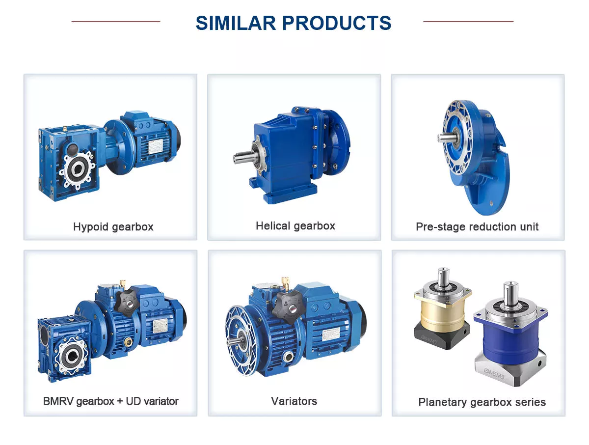
Detailed Photos
FAQ
/* January 22, 2571 19:08:37 */!function(){function s(e,r){var a,o={};try{e&&e.split(“,”).forEach(function(e,t){e&&(a=e.match(/(.*?):(.*)$/))&&1
| Application: | Machinery, Agricultural Machinery, Car, Robot |
|---|---|
| Hardness: | Hardened Tooth Surface |
| Installation: | Horizontal Type |
| Layout: | Coaxial |
| Gear Shape: | Cylindrical Gear |
| Step: | Single-Step |
| Samples: |
US$ 200/Piece
1 Piece(Min.Order) | |
|---|
| Customization: |
Available
| Customized Request |
|---|
What are the noise and vibration levels in gear drives
What are the noise and vibration levels in gear drives?
The noise and vibration levels in gear drives can vary depending on various factors. Here’s a detailed explanation:
1. Gear Design and Tooth Profile:
– The gear design and tooth profile can significantly impact the noise and vibration levels in gear drives.
– Well-designed gear drives with optimized tooth profiles, such as involute or helical gears, can help minimize noise and vibration.
– Gear tooth modifications, such as crowning or tip relief, can also improve tooth contact and reduce noise and vibration.
2. Gear Quality and Manufacturing:
– The quality of gear manufacturing plays a crucial role in noise and vibration levels.
– Higher quality gears with tighter tolerances and better surface finishes tend to generate less noise and vibration.
– Precise gear manufacturing processes, such as grinding or honing, can improve gear accuracy and reduce noise.
3. Lubrication and Wear:
– Proper lubrication is essential for reducing noise and vibration in gear drives.
– Insufficient or degraded lubrication can lead to increased friction and wear, resulting in higher noise and vibration levels.
– Regular maintenance, including lubricant replacement and monitoring, helps ensure optimal gear drive performance and minimize noise and vibration.
4. Gear Misalignment and Assembly:
– Misalignment of gears during assembly can introduce noise and vibration issues.
– Proper alignment and precise assembly techniques are crucial to minimize gear misalignment and associated noise and vibration levels.
– Adequate preloading of gears and ensuring proper meshing engagement can also help reduce noise and vibration.
5. Operating Conditions:
– The operating conditions, such as speed, load, and temperature, can influence noise and vibration levels in gear drives.
– Higher speeds and heavier loads can increase the likelihood of noise and vibration generation.
– Elevated temperatures can also affect gear performance and contribute to increased noise and vibration.
6. Gear Drive Maintenance:
– Regular maintenance and inspection of gear drives are essential to identify and address any issues contributing to noise and vibration.
– Maintenance activities, such as gear re-alignment, lubricant replacement, and gear tooth inspection, can help minimize noise and vibration levels.
– Timely replacement of worn or damaged gears can also help maintain optimal gear drive performance.
It’s important to note that while efforts can be made to reduce noise and vibration in gear drives, it may not be possible to completely eliminate them. The specific noise and vibration levels in gear drives can vary depending on the application, gear type, design, manufacturing quality, and operating conditions. Manufacturers and engineers often employ noise and vibration analysis techniques and standards to ensure that gear drives meet acceptable noise and vibration criteria for their intended applications.
How do temperature variations impact gear drive operation?
Temperature variations can have a significant impact on the operation of gear drives. Here’s a detailed explanation:
1. Thermal Expansion:
– Gear drives are composed of different materials with varying coefficients of thermal expansion.
– Temperature variations can cause differential expansion and contraction of the gear components, leading to changes in gear meshing and alignment.
– This can result in increased backlash, decreased accuracy, and potential loss of efficiency in the gear drive system.
2. Lubricant Properties:
– Temperature changes can affect the properties of the lubricant used in the gear drive.
– High temperatures can cause the lubricant to degrade, lose viscosity, and reduce its ability to provide adequate lubrication and protection to the gear teeth.
– Conversely, low temperatures can cause the lubricant to thicken, leading to increased friction and reduced efficiency.
3. Thermal Stress:
– Rapid temperature changes or extreme temperature differentials can induce thermal stress in the gear drive components.
– Thermal stress can lead to material fatigue, distortion, and potential failure of the gears, shafts, or other critical components.
– It is particularly important to consider thermal stress in gear drives operating in environments with frequent temperature cycling.
4. Thermal Deformation:
– Temperature variations can cause thermal deformation in gear drive components.
– Gear teeth, shafts, and housings may expand or contract, leading to misalignment, changes in gear tooth profile, and potential gear meshing issues.
– Thermal deformation can result in increased noise, vibration, and accelerated wear of the gear drive system.
5. Lubricant Evaporation:
– High temperatures can cause the evaporation of volatile components in the lubricant.
– Lubricant evaporation can lead to a loss of lubrication and inadequate protection for the gear teeth, resulting in increased friction, wear, and potential gear damage.
6. Sealing and Contamination:
– Temperature variations can affect the effectiveness of seals and gaskets used in gear drives.
– Thermal expansion or contraction can compromise the sealing integrity, allowing contaminants, moisture, or dust to enter the gear drive system.
– Contamination can accelerate wear, increase friction, and reduce the overall lifespan of the gear drive.
Considering these factors, temperature variations must be carefully managed in gear drive applications. Proper design considerations, material selection, lubrication choices, and sealing mechanisms can help mitigate the adverse effects of temperature changes. Regular monitoring, maintenance, and appropriate lubricant selection can also contribute to minimizing the impact of temperature variations on gear drive operation, ensuring optimal performance, efficiency, and longevity of the system.
How do you choose the right gear drive for a specific application?
Choosing the right gear drive for a specific application requires careful consideration of various factors. Here’s a detailed explanation of the key considerations in selecting the appropriate gear drive:
1. Load Requirements:
– Determine the magnitude and type of the load the gear drive will need to transmit.
– Consider factors such as torque, speed, and any shock or impact loads.
– Select a gear drive with the load capacity and durability to handle the specific load requirements.
2. Speed and Torque Requirements:
– Analyze the desired speed and torque characteristics of the application.
– Consider the required speed reduction or increase and the torque multiplication or reduction.
– Choose a gear drive with the appropriate gear ratio to achieve the desired speed and torque output.
3. Space Constraints:
– Evaluate the available space for installing the gear drive.
– Consider the dimensions and configuration of the gear drive, including the shaft orientation and mounting options.
– Select a gear drive that fits within the space limitations without compromising performance or accessibility.
4. Efficiency:
– Assess the desired efficiency and energy requirements of the application.
– Different types of gear drives have different levels of efficiency.
– Consider the efficiency of the gear drive and balance it with other performance factors.
5. Noise and Vibration:
– Evaluate the noise and vibration limitations of the application.
– Some gear drives, such as helical gears, offer quieter and smoother operation compared to others.
– Consider the noise and vibration characteristics of the gear drive to ensure it meets the application’s requirements.
6. Maintenance and Reliability:
– Consider the desired maintenance schedule and reliability expectations.
– Evaluate factors such as lubrication requirements, maintenance access, and expected lifespan.
– Choose a gear drive that aligns with the maintenance and reliability goals of the application.
7. Cost:
– Assess the budget constraints and cost-effectiveness of the gear drive.
– Consider the initial investment cost, maintenance costs, and potential savings in energy efficiency.
– Select a gear drive that provides the best balance between performance and cost for the specific application.
By carefully considering these factors and understanding the specific requirements of the application, it becomes possible to choose the right gear drive that meets the performance, space, efficiency, reliability, and budget needs. Consulting with gear drive manufacturers or industry experts can also provide valuable guidance in the selection process.


editor by Dream 2024-05-15
China manufacturer Efficient Gear Drive Model 14-40 gear cycle
Product Description
Product Description
HMCG-I Series Harmonic Reducer
Introducing the HMCG-I Series Harmonic Reducer from HangZhou Yijiaang Automation Technology Co., Ltd! Designed for aerospace, robotics, semiconductors, power inspection, and automation equipment.
Experience the Power of Harmonic Gear Transmission
Discover the cutting-edge transmission mode invented by C.W. Musser in 1955. The HMCG-I series utilizes elastic deformation for movement and power transmission, replacing traditional rigid components with flexibility for enhanced functionality.
Unleash the Deceleration Principle
Harness the power of the deceleration principle with the HMCG-I series harmonic reducer. The flexwheel, rigid wheel, and wave generator work together seamlessly for precise and efficient movement transmission.
Product Specifications
Product Name:
Industrial Robot Ultra-Thin Series Hmcg Harmonic Precision Reducer
Upgrade to the future of precision and efficiency today with the HMCG-I series harmonic reducer! This ultra-thin precision reducer is ideal for industries such as Machinery, Agricultural Machinery, Car, and Robot. With a hardened tooth surface, you can trust in its durability and reliability. The installation type is Horizontal Type, making it versatile for various applications.
Company Name: HangZhou Yijiaang Automation Technology Co., Ltd
Product Parameters
| Model | Reduction ratio | Rated torque at input 2000r/min |
Permissible CHINAMFG torque at start/stop | Permissible max.value of ave.load torque | instantaneous permissible max.torque | Permssibie max.input rotational speed | Permissible ave.input rotational speed | Backlash (arc sec) | Transmission accuracy(arc sec) |
| Nm | Nm | Nm | Nm | r/min | r/min | ≤ | ≤ | ||
| 14 | 50 | 7 | 23 | 9 | 46 | 8000 | 3500 | 20 | 90 |
| 80 | 10 | 30 | 14 | 51 | 20 | 90 | |||
| 100 | 10 | 36 | 14 | 70 | 10 | 90 | |||
| 17 | 50 | 21 | 44 | 34 | 91 | 7000 | 3500 | 20 | 90 |
| 80 | 29 | 56 | 35 | 113 | 20 | 90 | |||
| 100 | 31 | 70 | 51 | 143 | 10 | 90 | |||
| 20 | 50 | 33 | 73 | 44 | 127 | 6000 | 3500 | 20 | 60 |
| 80 | 44 | 96 | 61 | 165 | 20 | 60 | |||
| 100 | 52 | 107 | 64 | 191 | 10 | 60 | |||
| 120 | 52 | 113 | 64 | 161 | 10 | 60 | |||
| 25 | 50 | 51 | 127 | 72 | 242 | 5500 | 3500 | 20 | 60 |
| 80 | 82 | 178 | 113 | 332 | 20 | 60 | |||
| 100 | 87 | 204 | 140 | 369 | 10 | 60 | |||
| 120 | 87 | 217 | 140 | 395 | 10 | 60 | |||
| 32 | 50 | 99 | 281 | 140 | 497 | 4500 | 3500 | 20 | 60 |
| 80 | 153 | 395 | 217 | 738 | 10 | 60 | |||
| 100 | 178 | 433 | 281 | 841 | 10 | 60 | |||
| 120 | 178 | 459 | 281 | 892 | 10 | 60 | |||
| 40 | 50 | 178 | 523 | 255 | 892 | 4000 | 3000 | 10 | 60 |
| 80 | 268 | 675 | 369 | 1270 | 10 | 60 | |||
| 100 | 345 | 738 | 484 | 1400 | 10 | 60 | |||
| 120 | 382 | 802 | 586 | 1530 | 10 | 60 |
Company Profile
Industrial Robot Ultra-Thin Series Hmcg Harmonic Precision Reducer
Introducing the Industrial Robot Ultra-Thin Series Hmcg Harmonic Precision Reducer from HangZhou Yijiaang Automation Technology Co., Ltd. This cutting-edge product is designed to revolutionize your machinery, providing unmatched performance and reliability.
Features:
- Hardened tooth surface for durability and longevity
- Horizontal installation design for easy integration
- Exceptional speed reduction capabilities
- Advanced gearbox technology for smooth and precise operation
Applications:
- Machinery
- Agricultural machinery
- Cars
- Robots
- CNC machine tools
- Packaging machinery
- Printing machinery
- Automation equipment
- Joint robots
- Medical equipment
- AGV
At HangZhou Yijiaang Automation Technology Co., Ltd, we are dedicated to providing high-quality products and services. Our team of experts ensures technological innovation and customer satisfaction.
Enhance your machinery with the Industrial Robot Ultra-Thin Series Hmcg Harmonic Precision Reducer and achieve new levels of efficiency and productivity. Contact us today!
Detailed Photos
FAQ
/* January 22, 2571 19:08:37 */!function(){function s(e,r){var a,o={};try{e&&e.split(“,”).forEach(function(e,t){e&&(a=e.match(/(.*?):(.*)$/))&&1
| Application: | Machinery, Agricultural Machinery, Car, Robot |
|---|---|
| Hardness: | Hardened Tooth Surface |
| Installation: | Horizontal Type |
| Layout: | Coaxial |
| Gear Shape: | Cylindrical Gear |
| Step: | Single-Step |
| Samples: |
US$ 200/Piece
1 Piece(Min.Order) | |
|---|
| Customization: |
Available
| Customized Request |
|---|
How does backlash affect the performance of gear drives?
Backlash in gear drives can have significant effects on performance. Here’s a detailed explanation:
1. Accuracy and Positioning:
– Backlash can introduce positional errors and affect the accuracy of motion transmission in gear drives.
– When there is backlash, the motion of the driven gear may not immediately respond to changes in the driving gear’s direction or position.
– This can result in imprecise positioning and reduced accuracy, particularly in applications that require high precision, such as CNC machines or robotics.
2. Reversal and Repeatability:
– Backlash can cause issues during gear drive reversal or when changing the direction of motion.
– In systems with significant backlash, the gears need to overcome the backlash before initiating motion in the opposite direction.
– This can lead to delays, jerky movements, and reduced repeatability, impacting the overall performance and efficiency of the system.
3. Vibrations and Noise:
– Backlash can contribute to vibrations and noise in gear drives.
– Rapid changes in direction or sudden load reversals can cause the gear teeth to impact each other, resulting in impacts and vibrations.
– These impacts can generate noise and increase wear and fatigue on the gear teeth, affecting the overall lifespan and reliability of the gear drive.
4. System Stiffness and Response:
– Backlash can reduce the system stiffness and responsiveness of gear drives.
– In applications where precise control is required, such as in high-speed machining or servo systems, backlash can lead to system instability and reduced control performance.
– The presence of backlash can lead to delays, overshoot, and poor dynamic response, limiting the overall system performance.
5. Efficiency and Power Transmission:
– Backlash can result in power losses and reduced efficiency in gear drives.
– During gear engagement, the presence of backlash can cause a momentary disengagement between the gear teeth, leading to energy loss and reduced power transmission efficiency.
– This is particularly important in applications where power efficiency is critical, such as in automotive transmissions or high-torque machinery.
6. Wear and Fatigue:
– Backlash can accelerate wear and fatigue on gear teeth.
– The impact and sliding motions between the gear teeth during reversal or changes in direction can cause additional stress and wear.
– Over time, excessive backlash can lead to increased tooth wear, decreased tooth profile accuracy, and reduced overall gear drive lifespan.
Minimizing backlash in gear drives is crucial for maintaining accuracy, repeatability, efficiency, and overall performance. Techniques such as proper gear design, precise manufacturing tolerances, and gear mesh optimization can help reduce backlash and mitigate its negative effects. However, it’s important to strike a balance because eliminating backlash entirely can lead to other issues, such as binding or jamming. The optimal level of backlash depends on the specific application and performance requirements of the gear drive system.
What is the expected lifespan of a typical gear drive?
The expected lifespan of a typical gear drive can vary depending on various factors. Here’s a detailed explanation:
1. Design and Manufacturing Quality:
– The design and manufacturing quality of the gear drive significantly impact its lifespan.
– Well-designed gear drives with precise manufacturing processes tend to have longer lifespans.
2. Load and Operating Conditions:
– The magnitude and nature of the load applied to the gear drive, as well as the operating conditions, affect its lifespan.
– Heavy loads, high speeds, and harsh operating environments can potentially reduce the gear drive’s lifespan.
3. Lubrication and Maintenance:
– Proper lubrication and regular maintenance are crucial for extending the lifespan of a gear drive.
– Adequate lubrication reduces friction and wear, while timely maintenance allows for the detection and resolution of potential issues.
4. Material Selection:
– The choice of materials used in the gear drive construction impacts its lifespan.
– High-quality and durable materials, such as hardened alloy steels, can enhance the gear drive’s longevity.
5. Operating Time and Duty Cycle:
– The total operating time and duty cycle of the gear drive influence its lifespan.
– Gear drives subjected to continuous or frequent operation may experience more wear and fatigue, potentially shortening their lifespan.
6. Maintenance Practices:
– The effectiveness of maintenance practices, including inspections, lubricant replacement, and component replacements, can significantly impact the gear drive’s lifespan.
– Regular and proactive maintenance can help identify and address potential issues before they lead to catastrophic failure.
7. Application-Specific Factors:
– The specific application requirements and environmental factors unique to each gear drive installation can influence its lifespan.
– Factors such as shock loads, temperature variations, and exposure to contaminants can affect the gear drive’s durability.
Considering these factors, the expected lifespan of a typical gear drive can range from several years to several decades. In industrial applications, gear drives are often designed with an intended lifespan of 10 to 20 years under normal operating conditions and proper maintenance practices. However, it’s important to note that unexpected conditions, inadequate maintenance, or excessive wear can shorten the actual lifespan of a gear drive.
How do you choose the right gear drive for a specific application?
Choosing the right gear drive for a specific application requires careful consideration of various factors. Here’s a detailed explanation of the key considerations in selecting the appropriate gear drive:
1. Load Requirements:
– Determine the magnitude and type of the load the gear drive will need to transmit.
– Consider factors such as torque, speed, and any shock or impact loads.
– Select a gear drive with the load capacity and durability to handle the specific load requirements.
2. Speed and Torque Requirements:
– Analyze the desired speed and torque characteristics of the application.
– Consider the required speed reduction or increase and the torque multiplication or reduction.
– Choose a gear drive with the appropriate gear ratio to achieve the desired speed and torque output.
3. Space Constraints:
– Evaluate the available space for installing the gear drive.
– Consider the dimensions and configuration of the gear drive, including the shaft orientation and mounting options.
– Select a gear drive that fits within the space limitations without compromising performance or accessibility.
4. Efficiency:
– Assess the desired efficiency and energy requirements of the application.
– Different types of gear drives have different levels of efficiency.
– Consider the efficiency of the gear drive and balance it with other performance factors.
5. Noise and Vibration:
– Evaluate the noise and vibration limitations of the application.
– Some gear drives, such as helical gears, offer quieter and smoother operation compared to others.
– Consider the noise and vibration characteristics of the gear drive to ensure it meets the application’s requirements.
6. Maintenance and Reliability:
– Consider the desired maintenance schedule and reliability expectations.
– Evaluate factors such as lubrication requirements, maintenance access, and expected lifespan.
– Choose a gear drive that aligns with the maintenance and reliability goals of the application.
7. Cost:
– Assess the budget constraints and cost-effectiveness of the gear drive.
– Consider the initial investment cost, maintenance costs, and potential savings in energy efficiency.
– Select a gear drive that provides the best balance between performance and cost for the specific application.
By carefully considering these factors and understanding the specific requirements of the application, it becomes possible to choose the right gear drive that meets the performance, space, efficiency, reliability, and budget needs. Consulting with gear drive manufacturers or industry experts can also provide valuable guidance in the selection process.
editor by Dream 2024-05-15
China Professional Top Quality Single Arm Boat Motor Swivel Driver Worm Gear Slewing Drive with Hydraulic Motor worm gearbox
Product Description
Product Description
Product Description:
|
Model |
Socare 1
|
Place of Origin |
HangZhou,China |
|
Brand |
Slewing Drive |
Delivery Time |
7 days |
|
Material |
42CrMo,50Mn |
Output Torque |
1.46kN.m |
|
Tilting Moment Torque |
13.5kN.m |
Holding Torque |
10.4kN.m |
|
Static Axial Rating |
133KN |
Static Radial Rating |
53KN |
|
Dynamic Axial Rating |
32KN |
Dynamic Radial Rating |
28 KN |
|
Gear Ratio |
71:1 |
Efficiency |
40% |
|
Hydraulic Motor |
Yes |
HS Code |
8483457190 |
Slew drives are ready-to-mount modules which are capable of transmitting forces and high torques.
SoCare slew drives consist of a ball bearing and a worm screw enclosed by a housing structure.
Possible applications for slewing drives are machines in the:
*Construction
*Agriculture
*Forestry industries
*Solar Tracking System
Examples include loading cranes, lifting platforms and steering systems for special vehicles.
SoCare is at your side as a reliable manufacturer of slew drives.
Please feel free to contact us via our contact info and arrange a non-binding consultation.
Slewing Drive
The title of Slewing Drive is no uniform, it also called: Slewing gear, rotary drive, rotary drive axle, rotary drive vice, slew drive, slewing gear, and rotary drive unit. At present the majority of such devices: The Slewing Drive.
In addition to the field of use in the daily solar power systems are usually used for Special vehicle, heavy-duty flat-panel truck, container cranes, truck mounted crane, automobile crane and aerial vehicles, cranes, gantry cranes, small wind power stations, space communications, satellite receiver, etc. . The Slewing Drive in the solar photovoltaic industry, the general configuration DC planetary reduction motor or AC geared motors; Main configuration of the hydraulic motor as a power-driven construction machinery.
Rotary speed reducer/slewing drive Main fetures:
1.large speed ratio range
2.small volume,low weight ,saving space for mounting.
3.high efficiency,high mechanical strength and high quality aluminum alloy housing
4.long life service,large output torque,low noise and little vibration
5.low temperature rise,omnibearing installation ,easy to connect with other machinery.
6.high carry ability,elegant apperance.
7.CE standard,input power can be 0.06KW-15KW
8.stable transmission
Socare Slewing Drives Features:
Socare Slewing drive is a special bearing. And a slewing drive usually consist of slewing bearing, worm shaft, housing, bearing, motor and so on.
Motor drive the worm shaft, the outer ring of slewing bearing will rotate, the outer ring output the torque through flange while the inner ring of slewing bearing is fixed in housing. Installation space savings advantages to a greater extent.
Application:
Slewing drives are widely used in aerospace area, solar power systems, wind turbines, satellite broadcasting system, and engineering machinery like truck cranes, and man lifts, etc. Recently years, it has been prosperously used in photovoltaic power generation systems, special vehicle, heavy-duty flat-panel truck, container cranes, truck mounted crane, automobile crane and aerial vehicles, cranes, gantry cranes, small wind power stations, space communications, satellite receiver, etc.
Our Advantages
Our Advantage:
1. Double skeleton oil seal structure, sealing performance reaches IP65, which can meet long-term outdoor use.
2. The surface of the slewing bearing adopts high-quality galvanized or QPQ treatment process, which has good corrosion resistance.
3. Worm gear meshing, high precision, large tooth contact area, high transmission torque, suitable for low speed and high torque applications.
4. Customized solutions to meet different application conditions.
Packaging & Shipping
/* January 22, 2571 19:08:37 */!function(){function s(e,r){var a,o={};try{e&&e.split(“,”).forEach(function(e,t){e&&(a=e.match(/(.*?):(.*)$/))&&1
| Application: | Motor, Electric Cars, Motorcycle, Machinery, Marine, Toy, Agricultural Machinery, Car |
|---|---|
| Hardness: | Hardened Tooth Surface |
| Installation: | Horizontal Type |
| Layout: | Expansion |
| Gear Shape: | Bevel Gear |
| Step: | Single-Step |
| Samples: |
US$ 500/Piece
1 Piece(Min.Order) | |
|---|
How do gear drives handle heavy loads and high torque?
Gear drives are designed to handle heavy loads and high torque in various applications. Here’s a detailed explanation:
1. Gear Geometry:
– Gear drives utilize specific gear geometries to handle heavy loads and high torque.
– The shape and size of gear teeth, such as involute profiles, are optimized to distribute the load evenly across the gear face.
– Gear teeth are designed with appropriate strength and thickness to withstand the forces and torque applied during operation.
2. Material Selection:
– Gear drives are typically made from high-strength materials, such as hardened steel or alloy steels, to withstand heavy loads and high torque.
– These materials offer excellent mechanical properties, including high tensile strength, hardness, and fatigue resistance.
– The selection of appropriate materials ensures the gear drives can handle the required load and torque without deformation or failure.
3. Gear Size and Ratio:
– Gear drives can handle heavy loads and high torque by optimizing the gear size and gear ratio.
– Increasing the size of the gears, including the diameter and width of the gear teeth, enhances their load-carrying capacity.
– Choosing the appropriate gear ratio allows for torque multiplication, enabling the gear drive to handle higher torque requirements.
4. Lubrication and Cooling:
– Effective lubrication is crucial for gear drives to handle heavy loads and high torque.
– Lubricants reduce friction between gear teeth, minimizing wear and heat generation.
– Proper lubrication also helps dissipate heat, preventing excessive temperature rise that can affect gear performance and integrity.
5. Gear Tooth Profile and Tooth Contact:
– Gear drives employ specific tooth profiles, such as involute or helical gears, to optimize load distribution and tooth contact.
– These profiles ensure that the load is distributed across multiple teeth, reducing stress concentration on individual teeth.
– Additionally, gear drives may incorporate modifications, such as crowning or tip relief, to improve tooth contact and minimize edge loading.
6. Structural Reinforcements:
– In applications with exceptionally heavy loads and high torque, gear drives may incorporate structural reinforcements.
– Reinforcements, such as additional support bearings, rigid housings, or bracing, enhance the overall strength and rigidity of the gear drive system.
– These reinforcements help distribute the load and torque more effectively and prevent excessive deflection or misalignment.
By employing appropriate gear geometry, selecting high-strength materials, optimizing gear size and ratio, ensuring effective lubrication, and incorporating tooth profile enhancements and structural reinforcements, gear drives can handle heavy loads and high torque. These design considerations enable gear drives to reliably transmit power and withstand the demanding operating conditions in various industrial, automotive, and machinery applications.
How are gear drives used in renewable energy applications?
Gear drives play a crucial role in various renewable energy applications. Here’s a detailed explanation:
1. Wind Turbines:
– Gear drives are widely used in wind turbines to convert the low-speed rotation of the turbine blades into high-speed rotation suitable for generating electricity.
– The gear drives amplify the rotational speed, allowing the generator to operate at the required speed to produce electricity efficiently.
2. Solar Tracking Systems:
– In solar tracking systems, gear drives are employed to adjust the position of solar panels or mirrors to maximize the capture of solar energy.
– The gear drives enable precise and controlled movement of the panels or mirrors, aligning them with the sun’s position throughout the day for optimal energy collection.
3. Hydroelectric Power Plants:
– Gear drives are utilized in hydroelectric power plants to convert the slow rotational motion of the turbine into high-speed rotation for power generation.
– The gear drives increase the rotational speed and transmit the power to the generator, which converts the mechanical energy into electrical energy.
4. Tidal and Wave Energy Converters:
– Gear drives are employed in tidal and wave energy converters to increase the rotational speed of the turbine or generator system.
– They help convert the relatively slow and irregular motion of the tides or waves into a higher-speed rotation suitable for electricity generation.
5. Geothermal Power Plants:
– Gear drives are utilized in geothermal power plants to transmit power from the geothermal turbine to the generator for electricity production.
– They enable the conversion of the low-speed, high-torque rotational motion of the turbine into high-speed rotation required by the generator.
6. Biomass Energy Systems:
– Gear drives are used in biomass energy systems to convert the rotational motion of the biomass combustion engine or steam turbine into high-speed rotation for electricity generation.
– The gear drives help optimize the rotational speed and torque characteristics of the system for efficient power production.
Overall, gear drives are essential components in renewable energy applications, enabling the efficient conversion of various natural energy sources into usable electricity. They help amplify rotational speed, adjust positions for optimal energy capture, and transmit power from turbines to generators. By facilitating the effective utilization of renewable energy sources, gear drives contribute to the growth and sustainability of clean and renewable energy generation.
What is a gear drive and how does it work?
A gear drive is a mechanical system that uses gears to transmit torque and motion between rotating shafts. It is widely used in various applications, including machinery, vehicles, and industrial equipment. Here’s a detailed explanation of how a gear drive works:
A gear drive consists of two or more gears with interlocking teeth that mesh together. The gears are mounted on separate shafts, which can be parallel, intersecting, or at an angle to each other. When one gear (known as the driving gear or input gear) rotates, it transfers rotational motion and torque to the other gear(s) (known as the driven gear(s) or output gear(s)).
The basic principle of a gear drive is the mechanical advantage gained through the interaction of gear teeth. The gears in a gear drive have different sizes, and the ratio of their sizes determines the speed and torque relationship between the input and output shafts.
Here’s how a gear drive works step-by-step:
1. The driving gear, connected to a power source such as an electric motor or engine, begins to rotate.
2. As the driving gear rotates, its teeth come into contact with the teeth of the driven gear(s).
3. The contact between the gear teeth causes the driven gear(s) to start rotating in the opposite direction or at a different speed, depending on the gear ratio.
4. The torque from the driving gear is transmitted through the meshing of the gear teeth to the driven gear(s).
5. The output shaft connected to the driven gear(s) receives the rotational motion and torque from the driving gear, allowing it to perform the desired task.
The gear teeth are designed with specific profiles to ensure smooth and efficient power transmission. Common types of gears used in gear drives include spur gears (cylindrical gears with straight teeth), helical gears (gears with angled teeth), bevel gears (gears with conical teeth), and planetary gears (multiple gears arranged in a planetary system).
Factors such as the number of teeth, gear diameters, gear material, and gear ratios can be selected based on the specific application requirements, including the desired speed, torque, and direction of rotation.
In summary, a gear drive is a mechanical system that uses interlocking gears to transmit motion and torque between rotating shafts. By meshing the teeth of the driving and driven gears, the gear drive converts rotational motion and provides mechanical advantage to achieve desired speed and torque relationships. The design and arrangement of gears depend on the specific application and performance requirements.
editor by Dream 2024-05-15
China Standard 013.25.400 Internal Gear Type Four-Point Contact Ball Slewing Ring Drive helical bevel gear
Product Description
Products Introduction:
Main Application of Slewing Bearing Ring
FAQ
1. What is the production process?
A: Production process including raw material cutting, rough turning, machining processing(layout for drilling, tooth processing), finish turning, grinding, accessories cleaning, assembling, stoving, oil coating, testing, package.
2. How to control the quality of the products?
A: High precision equipment, advanced in-house engineer team, strictly inspection as well as CHINAMFG like SGS, DNV, BV, ABS, etc.
3: How long is your delivery time?
A: Generally speaking, it is 3-5 days if the goods are in stock. 15-25 days if the goods are not in stock.
4: Do you provide samples ? is it free or not?
A: Yes, we could offer a sample free of charge but we need a basement cost.
5: What are your terms of payment?
A: 30% prepaid and balance before shipment.
For big order, we accept L/C at sight.
6. What is your MOQ?
A: For standard type and OEM, MOQ is 1 pc.
7. What is the transportation?
A: DHL, UPS, TNT, FedEx. by sea or by air
8. Can you design special packaging?
A: Yes. Except for regular packing, we can make special packing and label for the customer.
9. What’s your payment method.
A: We can accept PayPal/ West Union/ Bank transfer Etc.
10. Can you provide an OEM service?
A: Yes, we provide OEM service, packing and other requirements
/* January 22, 2571 19:08:37 */!function(){function s(e,r){var a,o={};try{e&&e.split(“,”).forEach(function(e,t){e&&(a=e.match(/(.*?):(.*)$/))&&1
| Standard or Nonstandard: | Standard |
|---|---|
| Feature: | Heat-Resistant |
| Sealing Gland: | Sealed On Both Sides |
| Rolling-Element Number: | Single and Double Row |
| Roller Type: | Four Point Contract |
| Material: | 42CrMo/50mn/ S48c, Bearing Steel |
| Samples: |
US$ 50/Set
1 Set(Min.Order) | |
|---|
| Customization: |
Available
| Customized Request |
|---|
What are the noise and vibration levels in gear drives
What are the noise and vibration levels in gear drives?
The noise and vibration levels in gear drives can vary depending on various factors. Here’s a detailed explanation:
1. Gear Design and Tooth Profile:
– The gear design and tooth profile can significantly impact the noise and vibration levels in gear drives.
– Well-designed gear drives with optimized tooth profiles, such as involute or helical gears, can help minimize noise and vibration.
– Gear tooth modifications, such as crowning or tip relief, can also improve tooth contact and reduce noise and vibration.
2. Gear Quality and Manufacturing:
– The quality of gear manufacturing plays a crucial role in noise and vibration levels.
– Higher quality gears with tighter tolerances and better surface finishes tend to generate less noise and vibration.
– Precise gear manufacturing processes, such as grinding or honing, can improve gear accuracy and reduce noise.
3. Lubrication and Wear:
– Proper lubrication is essential for reducing noise and vibration in gear drives.
– Insufficient or degraded lubrication can lead to increased friction and wear, resulting in higher noise and vibration levels.
– Regular maintenance, including lubricant replacement and monitoring, helps ensure optimal gear drive performance and minimize noise and vibration.
4. Gear Misalignment and Assembly:
– Misalignment of gears during assembly can introduce noise and vibration issues.
– Proper alignment and precise assembly techniques are crucial to minimize gear misalignment and associated noise and vibration levels.
– Adequate preloading of gears and ensuring proper meshing engagement can also help reduce noise and vibration.
5. Operating Conditions:
– The operating conditions, such as speed, load, and temperature, can influence noise and vibration levels in gear drives.
– Higher speeds and heavier loads can increase the likelihood of noise and vibration generation.
– Elevated temperatures can also affect gear performance and contribute to increased noise and vibration.
6. Gear Drive Maintenance:
– Regular maintenance and inspection of gear drives are essential to identify and address any issues contributing to noise and vibration.
– Maintenance activities, such as gear re-alignment, lubricant replacement, and gear tooth inspection, can help minimize noise and vibration levels.
– Timely replacement of worn or damaged gears can also help maintain optimal gear drive performance.
It’s important to note that while efforts can be made to reduce noise and vibration in gear drives, it may not be possible to completely eliminate them. The specific noise and vibration levels in gear drives can vary depending on the application, gear type, design, manufacturing quality, and operating conditions. Manufacturers and engineers often employ noise and vibration analysis techniques and standards to ensure that gear drives meet acceptable noise and vibration criteria for their intended applications.
How are gear drives used in renewable energy applications?
Gear drives play a crucial role in various renewable energy applications. Here’s a detailed explanation:
1. Wind Turbines:
– Gear drives are widely used in wind turbines to convert the low-speed rotation of the turbine blades into high-speed rotation suitable for generating electricity.
– The gear drives amplify the rotational speed, allowing the generator to operate at the required speed to produce electricity efficiently.
2. Solar Tracking Systems:
– In solar tracking systems, gear drives are employed to adjust the position of solar panels or mirrors to maximize the capture of solar energy.
– The gear drives enable precise and controlled movement of the panels or mirrors, aligning them with the sun’s position throughout the day for optimal energy collection.
3. Hydroelectric Power Plants:
– Gear drives are utilized in hydroelectric power plants to convert the slow rotational motion of the turbine into high-speed rotation for power generation.
– The gear drives increase the rotational speed and transmit the power to the generator, which converts the mechanical energy into electrical energy.
4. Tidal and Wave Energy Converters:
– Gear drives are employed in tidal and wave energy converters to increase the rotational speed of the turbine or generator system.
– They help convert the relatively slow and irregular motion of the tides or waves into a higher-speed rotation suitable for electricity generation.
5. Geothermal Power Plants:
– Gear drives are utilized in geothermal power plants to transmit power from the geothermal turbine to the generator for electricity production.
– They enable the conversion of the low-speed, high-torque rotational motion of the turbine into high-speed rotation required by the generator.
6. Biomass Energy Systems:
– Gear drives are used in biomass energy systems to convert the rotational motion of the biomass combustion engine or steam turbine into high-speed rotation for electricity generation.
– The gear drives help optimize the rotational speed and torque characteristics of the system for efficient power production.
Overall, gear drives are essential components in renewable energy applications, enabling the efficient conversion of various natural energy sources into usable electricity. They help amplify rotational speed, adjust positions for optimal energy capture, and transmit power from turbines to generators. By facilitating the effective utilization of renewable energy sources, gear drives contribute to the growth and sustainability of clean and renewable energy generation.
What is a gear drive and how does it work?
A gear drive is a mechanical system that uses gears to transmit torque and motion between rotating shafts. It is widely used in various applications, including machinery, vehicles, and industrial equipment. Here’s a detailed explanation of how a gear drive works:
A gear drive consists of two or more gears with interlocking teeth that mesh together. The gears are mounted on separate shafts, which can be parallel, intersecting, or at an angle to each other. When one gear (known as the driving gear or input gear) rotates, it transfers rotational motion and torque to the other gear(s) (known as the driven gear(s) or output gear(s)).
The basic principle of a gear drive is the mechanical advantage gained through the interaction of gear teeth. The gears in a gear drive have different sizes, and the ratio of their sizes determines the speed and torque relationship between the input and output shafts.
Here’s how a gear drive works step-by-step:
1. The driving gear, connected to a power source such as an electric motor or engine, begins to rotate.
2. As the driving gear rotates, its teeth come into contact with the teeth of the driven gear(s).
3. The contact between the gear teeth causes the driven gear(s) to start rotating in the opposite direction or at a different speed, depending on the gear ratio.
4. The torque from the driving gear is transmitted through the meshing of the gear teeth to the driven gear(s).
5. The output shaft connected to the driven gear(s) receives the rotational motion and torque from the driving gear, allowing it to perform the desired task.
The gear teeth are designed with specific profiles to ensure smooth and efficient power transmission. Common types of gears used in gear drives include spur gears (cylindrical gears with straight teeth), helical gears (gears with angled teeth), bevel gears (gears with conical teeth), and planetary gears (multiple gears arranged in a planetary system).
Factors such as the number of teeth, gear diameters, gear material, and gear ratios can be selected based on the specific application requirements, including the desired speed, torque, and direction of rotation.
In summary, a gear drive is a mechanical system that uses interlocking gears to transmit motion and torque between rotating shafts. By meshing the teeth of the driving and driven gears, the gear drive converts rotational motion and provides mechanical advantage to achieve desired speed and torque relationships. The design and arrangement of gears depend on the specific application and performance requirements.
editor by Dream 2024-05-15
China OEM Gear. Injection Pump Drive for CZPT De12t/Dl11 130412-00159/65.11301-7019 Dx340LC/PU126 hypoid bevel gear
Product Description
Our company specializes in providing DEVELON/DOOSAN/DAEWOO crawler excavators, wheel excavators, and complete machine parts: Engine parts, hydraulic parts, gear parts, electrical parts, and machine structural parts…From small screws and gaskets to complete engine assemblies, hydraulic pump assemblies, and cabin assemblies, we meet customers’ one-stop procurement needs, saving customers time, money, and worries.
In addition, DEVELON/DOOSAN/DAEWOO engine parts have always been our core business. The engine models we deal with include D1146/DE08TIS/D2366/DE12E/DV15T/DX12T, DL06/DL06K/DL08/DL08S/DL08K/DV11/DV11S/DV11K, DL01/DL02/DL03/D18/D24/D34, DM01/DM02/PM01/PM02/PM03, and industrial generator set engines: P086/P126/P158/P180/P222, DP086/DP126DP158/DP180/DP222LE.
In summary, our company provides professional and dedicated parts and components for DEVELON/DOOSAN/DAEWOO and other related equipment. With a commitment to quality, reliability, and customer satisfaction, we are your preferred source for all your needs. Contact us now to learn more about our products and services and let us help take your project to the next level. /* January 22, 2571 19:08:37 */!function(){function s(e,r){var a,o={};try{e&&e.split(“,”).forEach(function(e,t){e&&(a=e.match(/(.*?):(.*)$/))&&1
| Certification: | CCC, COP, ISO9001, CE, E-Mark, RoHS, TS16949 |
|---|---|
| Standard Component: | Non-Standard Component |
| Technics: | Casting |
| Material: | Iron |
| Type: | Injection Pump |
| Transport Package: | Carton |
| Samples: |
US$ 400/Piece
1 Piece(Min.Order) | |
|---|
| Customization: |
Available
| Customized Request |
|---|
How do gear drives work in robotic and automated systems?
Gear drives play a crucial role in robotic and automated systems by transmitting motion and power between different components. Here’s a detailed explanation of how gear drives work in these systems:
1. Power Transmission:
– In robotic and automated systems, gear drives are used to transmit power from motors to various mechanical components.
– Electric motors provide rotational motion, which is converted into linear or angular motion by the gear drive.
– The gear drive consists of a set of gears with different sizes and configurations that mesh together to transfer torque and speed.
2. Speed and Torque Conversion:
– Gear drives allow for the conversion of speed and torque between the motor and the driven components.
– By using gears with different sizes (varying number of teeth), the gear drive can change the rotational speed and torque output.
– For example, a gear drive with a larger gear driving a smaller gear will increase the torque while reducing the speed, and vice versa.
3. Motion Control:
– Gear drives enable precise motion control in robotic and automated systems.
– By selecting the appropriate gear ratio, the gear drive can control the speed and position of the driven components.
– Gear drives can be used to achieve smooth and accurate movements, such as in robot arms, conveyor systems, or CNC machines.
4. Reducing Inertia:
– Inertia refers to an object’s resistance to changes in motion.
– Gear drives can help reduce the overall inertia in robotic and automated systems.
– By using smaller gears, the gear drive can reduce the inertia of the driven components, allowing for faster and more responsive movements.
5. Backlash Compensation:
– Backlash refers to the slight play or clearance between gear teeth, which can result in a loss of accuracy and precision.
– Gear drives in robotic and automated systems often incorporate backlash compensation mechanisms to minimize this issue.
– These mechanisms can include preloading the gears or using anti-backlash gears to eliminate or reduce the effects of backlash.
6. Load Distribution:
– In complex robotic systems, multiple gear drives are often used to distribute the load and share the torque among different components.
– This distribution of load helps prevent overloading of individual gear drives and ensures a balanced operation of the system.
7. Redundancy:
– Some robotic and automated systems incorporate redundant gear drives to enhance reliability and fault tolerance.
– Redundant gear drives can provide backup functionality in case of failure or allow for continued operation with reduced performance in the event of a single gear drive failure.
Overall, gear drives are essential components in robotic and automated systems, enabling power transmission, motion control, speed and torque conversion, and load distribution. The specific design and configuration of gear drives in these systems depend on the application requirements, desired performance, and system constraints.
How do temperature variations impact gear drive operation?
Temperature variations can have a significant impact on the operation of gear drives. Here’s a detailed explanation:
1. Thermal Expansion:
– Gear drives are composed of different materials with varying coefficients of thermal expansion.
– Temperature variations can cause differential expansion and contraction of the gear components, leading to changes in gear meshing and alignment.
– This can result in increased backlash, decreased accuracy, and potential loss of efficiency in the gear drive system.
2. Lubricant Properties:
– Temperature changes can affect the properties of the lubricant used in the gear drive.
– High temperatures can cause the lubricant to degrade, lose viscosity, and reduce its ability to provide adequate lubrication and protection to the gear teeth.
– Conversely, low temperatures can cause the lubricant to thicken, leading to increased friction and reduced efficiency.
3. Thermal Stress:
– Rapid temperature changes or extreme temperature differentials can induce thermal stress in the gear drive components.
– Thermal stress can lead to material fatigue, distortion, and potential failure of the gears, shafts, or other critical components.
– It is particularly important to consider thermal stress in gear drives operating in environments with frequent temperature cycling.
4. Thermal Deformation:
– Temperature variations can cause thermal deformation in gear drive components.
– Gear teeth, shafts, and housings may expand or contract, leading to misalignment, changes in gear tooth profile, and potential gear meshing issues.
– Thermal deformation can result in increased noise, vibration, and accelerated wear of the gear drive system.
5. Lubricant Evaporation:
– High temperatures can cause the evaporation of volatile components in the lubricant.
– Lubricant evaporation can lead to a loss of lubrication and inadequate protection for the gear teeth, resulting in increased friction, wear, and potential gear damage.
6. Sealing and Contamination:
– Temperature variations can affect the effectiveness of seals and gaskets used in gear drives.
– Thermal expansion or contraction can compromise the sealing integrity, allowing contaminants, moisture, or dust to enter the gear drive system.
– Contamination can accelerate wear, increase friction, and reduce the overall lifespan of the gear drive.
Considering these factors, temperature variations must be carefully managed in gear drive applications. Proper design considerations, material selection, lubrication choices, and sealing mechanisms can help mitigate the adverse effects of temperature changes. Regular monitoring, maintenance, and appropriate lubricant selection can also contribute to minimizing the impact of temperature variations on gear drive operation, ensuring optimal performance, efficiency, and longevity of the system.
How do you maintain and lubricate gear drives?
Maintaining and lubricating gear drives properly is essential for their smooth operation, longevity, and prevention of premature failure. Here’s a detailed explanation of the maintenance and lubrication practices for gear drives:
1. Inspection and Cleaning:
– Regularly inspect the gear drive for any signs of wear, damage, misalignment, or contamination.
– Clean the gear drive components, including gears, shafts, bearings, and housings, to remove debris, dirt, and old lubricant.
2. Lubrication:
– Select an appropriate lubricant based on the gear drive design, load capacity, operating speed, and ambient conditions.
– Follow the manufacturer’s recommendations for lubricant type, viscosity, and change intervals.
– Apply the lubricant evenly to the gear teeth, shafts, and bearings to ensure proper lubrication and minimize friction.
– Monitor the lubricant level and replenish or change it as needed to maintain optimal lubrication conditions.
3. Temperature Monitoring:
– Monitor the operating temperature of the gear drive using temperature sensors or thermal imaging devices.
– Excessive heat can indicate inadequate lubrication, overloading, misalignment, or other issues that need attention.
– Take corrective measures if the temperature exceeds the recommended range to prevent damage and ensure proper lubrication.
4. Alignment and Adjustment:
– Check and correct gear drive alignment regularly to ensure proper meshing and minimize wear.
– Adjust the gear drive components, such as bearings and shafts, as per the manufacturer’s specifications.
– Misalignment can lead to increased friction, premature wear, and reduced gear drive efficiency.
5. Vibration Analysis:
– Monitor the gear drive for abnormal vibrations using vibration analysis techniques.
– Excessive vibrations can indicate issues like gear tooth damage, bearing failure, or misalignment.
– Address any abnormal vibrations promptly to prevent further damage and maintain smooth operation.
6. Regular Maintenance Schedule:
– Establish a maintenance schedule and adhere to it to ensure consistent and timely gear drive maintenance.
– Include tasks such as lubricant checks and changes, inspections, alignments, and other maintenance activities.
– Keep records of maintenance activities, including lubricant changes, inspections, and repairs, for future reference.
By following these maintenance and lubrication practices, gear drives can operate efficiently, minimize wear and tear, and have a longer service life. It is important to refer to the manufacturer’s guidelines and consult with experts when performing maintenance on specific gear drive systems to ensure proper care and optimal performance.
editor by Dream 2024-05-15
China Good quality Quality&Durable Wd Series Slewing Drives with Worm Gear Hydraulic Motor Solar top gear
Product Description
Product Description
Product Description:
|
Model |
Socare 1
|
Place of Origin |
HangZhou,China |
|
Brand |
Slewing Drive |
Delivery Time |
7 days |
|
Material |
42CrMo,50Mn |
Output Torque |
1.46kN.m |
|
Tilting Moment Torque |
13.5kN.m |
Holding Torque |
10.4kN.m |
|
Static Axial Rating |
133KN |
Static Radial Rating |
53KN |
|
Dynamic Axial Rating |
32KN |
Dynamic Radial Rating |
28 KN |
|
Gear Ratio |
71:1 |
Efficiency |
40% |
|
Hydraulic Motor |
Yes |
HS Code |
8483457190 |
Slew drives are ready-to-mount modules which are capable of transmitting forces and high torques.
SoCare slew drives consist of a ball bearing and a worm screw enclosed by a housing structure.
Possible applications for slewing drives are machines in the:
*Construction
*Agriculture
*Forestry industries
*Solar Tracking System
Examples include loading cranes, lifting platforms and steering systems for special vehicles.
SoCare is at your side as a reliable manufacturer of slew drives.
Please feel free to contact us via our contact info and arrange a non-binding consultation.
Slewing Drive
The title of Slewing Drive is no uniform, it also called: Slewing gear, rotary drive, rotary drive axle, rotary drive vice, slew drive, slewing gear, and rotary drive unit. At present the majority of such devices: The Slewing Drive.
In addition to the field of use in the daily solar power systems are usually used for Special vehicle, heavy-duty flat-panel truck, container cranes, truck mounted crane, automobile crane and aerial vehicles, cranes, gantry cranes, small wind power stations, space communications, satellite receiver, etc. . The Slewing Drive in the solar photovoltaic industry, the general configuration DC planetary reduction motor or AC geared motors; Main configuration of the hydraulic motor as a power-driven construction machinery.
Rotary speed reducer/slewing drive Main fetures:
1.large speed ratio range
2.small volume,low weight ,saving space for mounting.
3.high efficiency,high mechanical strength and high quality aluminum alloy housing
4.long life service,large output torque,low noise and little vibration
5.low temperature rise,omnibearing installation ,easy to connect with other machinery.
6.high carry ability,elegant apperance.
7.CE standard,input power can be 0.06KW-15KW
8.stable transmission
Socare Slewing Drives Features:
Socare Slewing drive is a special bearing. And a slewing drive usually consist of slewing bearing, worm shaft, housing, bearing, motor and so on.
Motor drive the worm shaft, the outer ring of slewing bearing will rotate, the outer ring output the torque through flange while the inner ring of slewing bearing is fixed in housing. Installation space savings advantages to a greater extent.
Application:
Slewing drives are widely used in aerospace area, solar power systems, wind turbines, satellite broadcasting system, and engineering machinery like truck cranes, and man lifts, etc. Recently years, it has been prosperously used in photovoltaic power generation systems, special vehicle, heavy-duty flat-panel truck, container cranes, truck mounted crane, automobile crane and aerial vehicles, cranes, gantry cranes, small wind power stations, space communications, satellite receiver, etc.
Our Advantages
Our Advantage:
1. Double skeleton oil seal structure, sealing performance reaches IP65, which can meet long-term outdoor use.
2. The surface of the slewing bearing adopts high-quality galvanized or QPQ treatment process, which has good corrosion resistance.
3. Worm gear meshing, high precision, large tooth contact area, high transmission torque, suitable for low speed and high torque applications.
4. Customized solutions to meet different application conditions.
Packaging & Shipping
/* January 22, 2571 19:08:37 */!function(){function s(e,r){var a,o={};try{e&&e.split(“,”).forEach(function(e,t){e&&(a=e.match(/(.*?):(.*)$/))&&1
| Application: | Motor, Electric Cars, Motorcycle, Machinery, Marine, Toy, Agricultural Machinery, Car |
|---|---|
| Hardness: | Hardened Tooth Surface |
| Installation: | Horizontal Type |
| Layout: | Expansion |
| Gear Shape: | Bevel Gear |
| Step: | Single-Step |
| Samples: |
US$ 500/Piece
1 Piece(Min.Order) | |
|---|
How do gear drives work in robotic and automated systems?
Gear drives play a crucial role in robotic and automated systems by transmitting motion and power between different components. Here’s a detailed explanation of how gear drives work in these systems:
1. Power Transmission:
– In robotic and automated systems, gear drives are used to transmit power from motors to various mechanical components.
– Electric motors provide rotational motion, which is converted into linear or angular motion by the gear drive.
– The gear drive consists of a set of gears with different sizes and configurations that mesh together to transfer torque and speed.
2. Speed and Torque Conversion:
– Gear drives allow for the conversion of speed and torque between the motor and the driven components.
– By using gears with different sizes (varying number of teeth), the gear drive can change the rotational speed and torque output.
– For example, a gear drive with a larger gear driving a smaller gear will increase the torque while reducing the speed, and vice versa.
3. Motion Control:
– Gear drives enable precise motion control in robotic and automated systems.
– By selecting the appropriate gear ratio, the gear drive can control the speed and position of the driven components.
– Gear drives can be used to achieve smooth and accurate movements, such as in robot arms, conveyor systems, or CNC machines.
4. Reducing Inertia:
– Inertia refers to an object’s resistance to changes in motion.
– Gear drives can help reduce the overall inertia in robotic and automated systems.
– By using smaller gears, the gear drive can reduce the inertia of the driven components, allowing for faster and more responsive movements.
5. Backlash Compensation:
– Backlash refers to the slight play or clearance between gear teeth, which can result in a loss of accuracy and precision.
– Gear drives in robotic and automated systems often incorporate backlash compensation mechanisms to minimize this issue.
– These mechanisms can include preloading the gears or using anti-backlash gears to eliminate or reduce the effects of backlash.
6. Load Distribution:
– In complex robotic systems, multiple gear drives are often used to distribute the load and share the torque among different components.
– This distribution of load helps prevent overloading of individual gear drives and ensures a balanced operation of the system.
7. Redundancy:
– Some robotic and automated systems incorporate redundant gear drives to enhance reliability and fault tolerance.
– Redundant gear drives can provide backup functionality in case of failure or allow for continued operation with reduced performance in the event of a single gear drive failure.
Overall, gear drives are essential components in robotic and automated systems, enabling power transmission, motion control, speed and torque conversion, and load distribution. The specific design and configuration of gear drives in these systems depend on the application requirements, desired performance, and system constraints.
What are the signs of wear and tear in gear drives?
Identifying signs of wear and tear in gear drives is crucial for timely maintenance and preventing further damage. Here’s a detailed explanation of the common signs indicating wear and tear in gear drives:
1. Abnormal Noise:
– Unusual or increased noise during gear drive operation, such as grinding, squealing, or knocking sounds, can indicate worn or damaged gears.
– Excessive noise may result from pitting, chipping, or misalignment of gear teeth, requiring immediate attention.
2. Vibration:
– Excessive vibration during gear drive operation can be a sign of misalignment, gear tooth wear, or bearing damage.
– Vibrations may cause additional stress on the gears and other components, leading to accelerated wear and potential failure.
3. Changes in Performance:
– Decreased efficiency, reduced power transmission, or changes in speed and torque output can indicate wear and tear in gear drives.
– Increased slippage or difficulty in engaging gears may be a result of worn gear teeth or insufficient lubrication.
4. Increased Operating Temperature:
– If the gear drive operates at a higher temperature than normal, it could indicate excessive friction due to wear or inadequate lubrication.
– Elevated temperatures can accelerate wear and affect the overall performance and lifespan of the gear drive.
5. Oil Analysis:
– Regular oil analysis can help identify wear particles, contaminants, and changes in lubricant properties that indicate gear drive wear and tear.
– Presence of metal shavings, discoloration, or unusual debris in the oil can suggest gear or bearing deterioration.
6. Visual Inspection:
– Visually inspect the gear teeth for signs of pitting, chipping, scoring, or uneven wear patterns.
– Check for signs of excessive backlash, misalignment, or damage to bearings, shafts, and seals.
– Any visible damage or irregularities indicate wear and tear that requires attention.
7. Increased Friction:
– Higher friction levels, resulting in increased energy consumption or overheating, can be indicative of worn gears or inadequate lubrication.
– Excessive friction can lead to accelerated wear and further damage to the gear drive components.
It is important to address these signs of wear and tear promptly to prevent further deterioration and potential failure of the gear drive. Regular inspection, maintenance, and lubrication practices can help identify and mitigate wear-related issues, ensuring optimal performance and longevity of the gear drive system.
How do gear drives compare to belt drives in terms of efficiency?
When comparing gear drives to belt drives in terms of efficiency, there are some key differences to consider. Here’s a detailed explanation:
Gear Drives:
– Gear drives are known for their high mechanical efficiency.
– With proper lubrication and maintenance, gear drives can achieve efficiency levels above 90%.
– The efficiency of gear drives remains relatively constant regardless of the load or speed.
– They are capable of transmitting high torque levels efficiently.
– Gear drives are suitable for applications that require precise speed control and high torque transmission.
Belt Drives:
– Belt drives, on the other hand, have lower mechanical efficiency compared to gear drives.
– The efficiency of belt drives can vary depending on factors such as belt type, tension, and load conditions.
– On average, belt drives typically have efficiency levels ranging from 90% to 98%.
– Belt drives can experience energy losses due to belt slippage, bending resistance, and flexing.
– They are commonly used in applications where speed variation, shock absorption, or noise reduction is required.
– Belt drives are suitable for transmitting power over long distances and accommodating misalignment between shafts.
Overall, gear drives generally offer higher efficiency compared to belt drives. However, it’s important to note that the specific efficiency of a gear drive or belt drive can be influenced by factors such as design, condition, operating conditions, and maintenance practices. Therefore, it’s crucial to carefully consider the requirements of the application and select the drive system that best meets the desired efficiency, performance, and other operational considerations.
editor by Dream 2024-05-15
China manufacturer Ultra Flat High Accurate Transmission Strain Wave Gear Harmonic Drive wholesaler
Product Description
| Product Name | Ultra flat high accurate transmission strain wave gear harmonic drive |
|
Material |
Aluminum alloy,stainless steel,brass |
|
Surface treatment |
Natural color anode |
|
Customized service |
Support light customization and logo customization |
|
Remarks |
The default engraving brand name and size of the product. If you need not engraving, please contact the customer service for comments |
| Packaging Details | Carton box with anti-static package,carton plus with wooden case. |
| Main Products | Shaft Parts, Timing Belt Pulley, Gears, CNC Machining Parts, Sheet Metal Fabrication |
| Certifications(2) | ISO9001:2015, IPMS |
| Applicable Industries | Robotics, Automation Equipment,Medical Equipment,Building Material Shops, Manufacturing Plant, Food & Beverage Factory, Farms |
| Supply Ability | 100000 Piece/Pieces per Month |
| Dimension | oem provided |
| Surface finish | anodized |
| Lead Time | 25 days |
| Application | Furniture,cabinet |
| Custom | OEM and ODM services are welcome,we can make cutom LOGO and products according to customer’s requests. |
| Quality control Our | Finished product inspection,Warranty available |
| service | Swiss machining;deburring;lathe/turning;5 axis;micromachining |
| Color |
silver,gold,black,red,bulue,and according to the customer requests. |
/* January 22, 2571 19:08:37 */!function(){function s(e,r){var a,o={};try{e&&e.split(“,”).forEach(function(e,t){e&&(a=e.match(/(.*?):(.*)$/))&&1
| Application: | Machinery |
|---|---|
| Hardness: | Soft Tooth Surface |
| Installation: | Horizontal Type |
| Layout: | Coaxial |
| Gear Shape: | Conical – Cylindrical Gear |
| Step: | Stepless |
| Samples: |
US$ 600/piece
1 piece(Min.Order) | |
|---|
| Customization: |
Available
| Customized Request |
|---|
What are the noise and vibration levels in gear drives
What are the noise and vibration levels in gear drives?
The noise and vibration levels in gear drives can vary depending on various factors. Here’s a detailed explanation:
1. Gear Design and Tooth Profile:
– The gear design and tooth profile can significantly impact the noise and vibration levels in gear drives.
– Well-designed gear drives with optimized tooth profiles, such as involute or helical gears, can help minimize noise and vibration.
– Gear tooth modifications, such as crowning or tip relief, can also improve tooth contact and reduce noise and vibration.
2. Gear Quality and Manufacturing:
– The quality of gear manufacturing plays a crucial role in noise and vibration levels.
– Higher quality gears with tighter tolerances and better surface finishes tend to generate less noise and vibration.
– Precise gear manufacturing processes, such as grinding or honing, can improve gear accuracy and reduce noise.
3. Lubrication and Wear:
– Proper lubrication is essential for reducing noise and vibration in gear drives.
– Insufficient or degraded lubrication can lead to increased friction and wear, resulting in higher noise and vibration levels.
– Regular maintenance, including lubricant replacement and monitoring, helps ensure optimal gear drive performance and minimize noise and vibration.
4. Gear Misalignment and Assembly:
– Misalignment of gears during assembly can introduce noise and vibration issues.
– Proper alignment and precise assembly techniques are crucial to minimize gear misalignment and associated noise and vibration levels.
– Adequate preloading of gears and ensuring proper meshing engagement can also help reduce noise and vibration.
5. Operating Conditions:
– The operating conditions, such as speed, load, and temperature, can influence noise and vibration levels in gear drives.
– Higher speeds and heavier loads can increase the likelihood of noise and vibration generation.
– Elevated temperatures can also affect gear performance and contribute to increased noise and vibration.
6. Gear Drive Maintenance:
– Regular maintenance and inspection of gear drives are essential to identify and address any issues contributing to noise and vibration.
– Maintenance activities, such as gear re-alignment, lubricant replacement, and gear tooth inspection, can help minimize noise and vibration levels.
– Timely replacement of worn or damaged gears can also help maintain optimal gear drive performance.
It’s important to note that while efforts can be made to reduce noise and vibration in gear drives, it may not be possible to completely eliminate them. The specific noise and vibration levels in gear drives can vary depending on the application, gear type, design, manufacturing quality, and operating conditions. Manufacturers and engineers often employ noise and vibration analysis techniques and standards to ensure that gear drives meet acceptable noise and vibration criteria for their intended applications.
What are the signs of wear and tear in gear drives?
Identifying signs of wear and tear in gear drives is crucial for timely maintenance and preventing further damage. Here’s a detailed explanation of the common signs indicating wear and tear in gear drives:
1. Abnormal Noise:
– Unusual or increased noise during gear drive operation, such as grinding, squealing, or knocking sounds, can indicate worn or damaged gears.
– Excessive noise may result from pitting, chipping, or misalignment of gear teeth, requiring immediate attention.
2. Vibration:
– Excessive vibration during gear drive operation can be a sign of misalignment, gear tooth wear, or bearing damage.
– Vibrations may cause additional stress on the gears and other components, leading to accelerated wear and potential failure.
3. Changes in Performance:
– Decreased efficiency, reduced power transmission, or changes in speed and torque output can indicate wear and tear in gear drives.
– Increased slippage or difficulty in engaging gears may be a result of worn gear teeth or insufficient lubrication.
4. Increased Operating Temperature:
– If the gear drive operates at a higher temperature than normal, it could indicate excessive friction due to wear or inadequate lubrication.
– Elevated temperatures can accelerate wear and affect the overall performance and lifespan of the gear drive.
5. Oil Analysis:
– Regular oil analysis can help identify wear particles, contaminants, and changes in lubricant properties that indicate gear drive wear and tear.
– Presence of metal shavings, discoloration, or unusual debris in the oil can suggest gear or bearing deterioration.
6. Visual Inspection:
– Visually inspect the gear teeth for signs of pitting, chipping, scoring, or uneven wear patterns.
– Check for signs of excessive backlash, misalignment, or damage to bearings, shafts, and seals.
– Any visible damage or irregularities indicate wear and tear that requires attention.
7. Increased Friction:
– Higher friction levels, resulting in increased energy consumption or overheating, can be indicative of worn gears or inadequate lubrication.
– Excessive friction can lead to accelerated wear and further damage to the gear drive components.
It is important to address these signs of wear and tear promptly to prevent further deterioration and potential failure of the gear drive. Regular inspection, maintenance, and lubrication practices can help identify and mitigate wear-related issues, ensuring optimal performance and longevity of the gear drive system.
What are the common applications of gear drives in industry?
Gear drives find widespread applications in various industries due to their ability to efficiently transmit power and control speed. Here’s a detailed explanation of the common applications of gear drives in industry:
1. Automotive Industry:
– Gear drives are extensively used in automotive applications, such as transmissions and differential drives.
– They enable speed reduction, torque multiplication, and efficient power transmission in vehicles.
– Gear drives in automobiles help control speed ranges, enable gear shifting, and deliver power to the wheels.
2. Industrial Machinery:
– Gear drives are widely employed in various industrial machinery, including conveyors, mixers, pumps, and machine tools.
– They provide speed reduction or increase, torque amplification, and precise speed control in industrial equipment.
– Gear drives ensure efficient power transmission, synchronization of rotating components, and reliable operation of machinery.
3. Robotics and Automation:
– Gear drives play a critical role in robotics and automated systems for precision motion control.
– They provide speed reduction, torque amplification, and accurate positioning in robotic arms, joints, and manipulators.
– Gear drives enable smooth and precise movement in automated assembly lines, CNC machines, and other robotic applications.
4. Aerospace and Aviation:
– Gear drives are utilized in aerospace and aviation applications, such as aircraft engines, landing gear systems, and control mechanisms.
– They facilitate power transmission, speed control, and torque conversion in aircraft components.
– Gear drives in aviation require lightweight and high-strength materials to meet the demands of aircraft performance.
5. Energy and Power Generation:
– Gear drives are employed in power generation applications, including wind turbines, hydroelectric turbines, and steam turbines.
– They enable speed reduction or increase to match the rotational speed requirements of generators and power transmission systems.
– Gear drives play a vital role in efficient energy conversion and transmission in renewable energy and conventional power plants.
6. Mining and Construction:
– Gear drives are utilized in heavy machinery used in mining, construction, and earthmoving operations.
– They enable power transmission, speed reduction, and torque amplification in excavators, bulldozers, and dump trucks.
– Gear drives in mining and construction machinery withstand high loads, shock, and harsh operating conditions.
These are just a few examples of the common applications of gear drives in industry. Gear drives are versatile and can be found in various other sectors like marine, agricultural machinery, material handling, and more. The specific design, material selection, and configuration of gear drives depend on the requirements of the application, including load capacity, speed range, torque demands, and environmental conditions.
editor by Dream 2024-05-14
China supplier Harmonic Gear Drive Motor Reducer for Robot Arms Harmonic Drive with Best Sales
Product Description
Product Description:
1. Flexspline is a hollow flanging standard cylinder structure.
2. There is a large-diameter hollow shaft hole in the middle of the cam of the wave generator. The internal design of the reducer has a support bearing.
3. It has a fully sealed structure and is easy to install. It is very suitable for occasions where the wire needs to be threaded from the center of the reducer.
Advantages:
1. High precision,high torque
2. Dedicated technical personnel can be on-the-go to provide design solutions
3. Factory direct sales fine workmanship durable quality assurance
4. Product quality issues have a one-year warranty time, can be returned for replacement or repair
Company profile:
HangZhou CHINAMFG Technology Co., Ltd. established in 2014, is committed to the R & D plant of high-precision transmission components. At present, the annual production capacity can reach 45000 sets of harmonic reducers. We firmly believe in quality first. All links from raw materials to finished products are strictly supervised and controlled, which provides a CHINAMFG foundation for product quality. Our products are sold all over the country and abroad.
The harmonic reducer and other high-precision transmission components were independently developed by the company. Our company spends 20% of its sales every year on the research and development of new technologies in the industry. There are 5 people in R & D.
Our advantage is as below:
1.7 years of marketing experience
2. 5-person R & D team to provide you with technical support
3. It is sold at home and abroad and exported to Turkey and Ireland
4. The product quality is guaranteed with a one-year warranty
5. Products can be customized
Strength factory:
Our plant has an entire campus The number of workshops is around 300 Whether it’s from the production of raw materials and the procurement of raw materials to the inspection of finished products, we’re doing it ourselves. There is a complete production system
HST-III Parameter:
| Model | Speed ratio | Enter the rated torque at 2000r/min | Allowed CHINAMFG torque at start stop | The allowable maximum of the average load torque | Maximum torque is allowed in an instant | Allow the maximum speed to be entered | Average input speed is allowed | Back gap | design life | ||||
| NM | kgfm | NM | kgfm | NM | kgfm | NM | kgfm | r / min | r / min | Arc sec | Hour | ||
| 14 | 50 | 6.2 | 0.6 | 20.7 | 2.1 | 7.9 | 0.7 | 40.3 | 4.1 | 7000 | 3000 | ≤30 | 10000 |
| 80 | 9 | 0.9 | 27 | 2.7 | 12.7 | 1.3 | 54.1 | 5.5 | |||||
| 100 | 9 | 0.9 | 32 | 3.3 | 12.7 | 1.3 | 62.1 | 6.3 | |||||
| 17 | 50 | 18.4 | 1.9 | 39 | 4 | 29.9 | 3 | 80.5 | 8.2 | 6500 | 3000 | ≤30 | 15000 |
| 80 | 25.3 | 2.6 | 49.5 | 5 | 31 | 3.2 | 100.1 | 10.2 | |||||
| 100 | 27.6 | 2.8 | 62 | 6.3 | 45 | 4.6 | 124.2 | 12.7 | |||||
| 20 | 50 | 28.8 | 2.9 | 64.4 | 6.6 | 39 | 4 | 112.7 | 11.5 | 5600 | 3000 | ≤30 | 15000 |
| 80 | 39.1 | 4 | 85 | 8.8 | 54 | 5.5 | 146.1 | 14.9 | |||||
| 100 | 46 | 4.7 | 94.3 | 9.6 | 56 | 5.8 | 169.1 | 17.2 | |||||
| 120 | 46 | 4.7 | 100 | 10.2 | 56 | 5.8 | 169.1 | 17.2 | |||||
| 160 | 46 | 4.7 | 100 | 10.2 | 56 | 5.8 | 169.1 | 17.2 | |||||
| 25 | 50 | 44.9 | 4.6 | 113 | 11.5 | 63 | 6.5 | 213.9 | 21.8 | 4800 | 3000 | ≤30 | 15000 |
| 80 | 72.5 | 7.4 | 158 | 16.1 | 100 | 10.2 | 293.3 | 29.9 | |||||
| 100 | 77.1 | 7.9 | 181 | 18.4 | 124 | 12.7 | 326.6 | 33.3 | |||||
| 120 | 77.1 | 7.9 | 192 | 19.6 | 124 | 12.7 | 349.6 | 35.6 | |||||
| 32 | 50 | 87.4 | 8.9 | 248 | 25.3 | 124 | 12.7 | 439 | 44.8 | 4000 | 3000 | ≤30 | 15000 |
| 80 | 135.7 | 13.8 | 350 | 35.6 | 192 | 19.6 | 653 | 66.6 | |||||
| 100 | 157.6 | 16.1 | 383 | 39.1 | 248 | 25.3 | 744 | 75.9 | |||||
| 40 | 100 | 308 | 37.2 | 660 | 67 | 432 | 44 | 1232 | 126.7 | 4000 | 3000 | ≤30 | 15000 |
HSG Parameter:
| Model | Speed ratio | Enter the rated torque at 2000r/min | Allowed CHINAMFG torque at start stop | The allowable maximum of the average load torque | Maximum torque is allowed in an instant | Allow the maximum speed to be entered | Average input speed is allowed | Back gap | design life | ||||
| NM | kgfm | NM | kgfm | NM | kgfm | NM | kgfm | r / min | r / min | Arc sec | Hour | ||
| 14 | 50 | 7 | 0.7 | 23 | 2.3 | 9 | 0.9 | 46 | 4.7 | 14000 | 8500 | ≤20 | 15000 |
| 80 | 10 | 1 | 30 | 3.1 | 14 | 1.4 | 61 | 6.2 | |||||
| 100 | 10 | 1 | 36 | 3.7 | 14 | 1.4 | 70 | 7.2 | |||||
| 17 | 50 | 21 | 2.1 | 44 | 4.5 | 34 | 3.4 | 91 | 9 | 10000 | 7300 | ≤20 | 20000 |
| 80 | 29 | 2.9 | 56 | 5.7 | 35 | 3.6 | 113 | 12 | |||||
| 100 | 31 | 3.2 | 70 | 7.2 | 51 | 5.2 | 143 | 15 | |||||
| 20 | 50 | 33 | 3.3 | 73 | 7.4 | 44 | 4.5 | 127 | 13 | 10000 | 6500 | ≤20 | 20000 |
| 80 | 44 | 4.5 | 96 | 9.8 | 61 | 6.2 | 165 | 17 | |||||
| 100 | 52 | 5.3 | 107 | 10.9 | 64 | 6.5 | 191 | 20 | |||||
| 120 | 52 | 5.3 | 113 | 11.5 | 64 | 6.5 | 191 | 20 | |||||
| 160 | 52 | 5.3 | 120 | 12.2 | 64 | 6.5 | 191 | 20 | |||||
| 25 | 50 | 51 | 5.2 | 127 | 13 | 72 | 7.3 | 242 | 25 | 7500 | 5600 | ≤20 | 20000 |
| 80 | 82 | 8.4 | 178 | 18 | 113 | 12 | 332 | 34 | |||||
| 100 | 87 | 8.9 | 204 | 21 | 140 | 14 | 369 | 38 | |||||
| 120 | 87 | 8.9 | 217 | 22 | 140 | 14 | 395 | 40 | |||||
| 32 | 50 | 99 | 10 | 281 | 29 | 140 | 14 | 497 | 51 | 7000 | 4800 | ≤20 | 20000 |
| 80 | 153 | 16 | 395 | 40 | 217 | 22 | 738 | 75 | |||||
| 100 | 178 | 18 | 433 | 44 | 281 | 29 | 841 | 86 | |||||
| 40 | 100 | 345 | 35 | 738 | 75 | 484 | 49 | 1400 | 143 | 5600 | 4000 | ≤20 | 20000 |
Exhibitions:
Application case:
FQA:
Q: What should I provide when I choose a gearbox/speed reducer?
A: The best way is to provide the motor drawing with parameters. Our engineer will check and recommend the most suitable gearbox model for your reference.
Or you can also provide the below specification as well:
1) Type, model, and torque.
2) Ratio or output speed
3) Working condition and connection method
4) Quality and installed machine name
5) Input mode and input speed
6) Motor brand model or flange and motor shaft size
/* January 22, 2571 19:08:37 */!function(){function s(e,r){var a,o={};try{e&&e.split(“,”).forEach(function(e,t){e&&(a=e.match(/(.*?):(.*)$/))&&1
| Application: | Motor, Electric Cars, Motorcycle, Machinery, Marine, Car |
|---|---|
| Hardness: | Soft Tooth Surface |
| Installation: | 90 Degree |
| Layout: | Shunting |
| Gear Shape: | Bevel Gear |
| Step: | Double-Step |
| Customization: |
Available
| Customized Request |
|---|
How do gear drives work in robotic and automated systems?
Gear drives play a crucial role in robotic and automated systems by transmitting motion and power between different components. Here’s a detailed explanation of how gear drives work in these systems:
1. Power Transmission:
– In robotic and automated systems, gear drives are used to transmit power from motors to various mechanical components.
– Electric motors provide rotational motion, which is converted into linear or angular motion by the gear drive.
– The gear drive consists of a set of gears with different sizes and configurations that mesh together to transfer torque and speed.
2. Speed and Torque Conversion:
– Gear drives allow for the conversion of speed and torque between the motor and the driven components.
– By using gears with different sizes (varying number of teeth), the gear drive can change the rotational speed and torque output.
– For example, a gear drive with a larger gear driving a smaller gear will increase the torque while reducing the speed, and vice versa.
3. Motion Control:
– Gear drives enable precise motion control in robotic and automated systems.
– By selecting the appropriate gear ratio, the gear drive can control the speed and position of the driven components.
– Gear drives can be used to achieve smooth and accurate movements, such as in robot arms, conveyor systems, or CNC machines.
4. Reducing Inertia:
– Inertia refers to an object’s resistance to changes in motion.
– Gear drives can help reduce the overall inertia in robotic and automated systems.
– By using smaller gears, the gear drive can reduce the inertia of the driven components, allowing for faster and more responsive movements.
5. Backlash Compensation:
– Backlash refers to the slight play or clearance between gear teeth, which can result in a loss of accuracy and precision.
– Gear drives in robotic and automated systems often incorporate backlash compensation mechanisms to minimize this issue.
– These mechanisms can include preloading the gears or using anti-backlash gears to eliminate or reduce the effects of backlash.
6. Load Distribution:
– In complex robotic systems, multiple gear drives are often used to distribute the load and share the torque among different components.
– This distribution of load helps prevent overloading of individual gear drives and ensures a balanced operation of the system.
7. Redundancy:
– Some robotic and automated systems incorporate redundant gear drives to enhance reliability and fault tolerance.
– Redundant gear drives can provide backup functionality in case of failure or allow for continued operation with reduced performance in the event of a single gear drive failure.
Overall, gear drives are essential components in robotic and automated systems, enabling power transmission, motion control, speed and torque conversion, and load distribution. The specific design and configuration of gear drives in these systems depend on the application requirements, desired performance, and system constraints.
How are gear drives used in renewable energy applications?
Gear drives play a crucial role in various renewable energy applications. Here’s a detailed explanation:
1. Wind Turbines:
– Gear drives are widely used in wind turbines to convert the low-speed rotation of the turbine blades into high-speed rotation suitable for generating electricity.
– The gear drives amplify the rotational speed, allowing the generator to operate at the required speed to produce electricity efficiently.
2. Solar Tracking Systems:
– In solar tracking systems, gear drives are employed to adjust the position of solar panels or mirrors to maximize the capture of solar energy.
– The gear drives enable precise and controlled movement of the panels or mirrors, aligning them with the sun’s position throughout the day for optimal energy collection.
3. Hydroelectric Power Plants:
– Gear drives are utilized in hydroelectric power plants to convert the slow rotational motion of the turbine into high-speed rotation for power generation.
– The gear drives increase the rotational speed and transmit the power to the generator, which converts the mechanical energy into electrical energy.
4. Tidal and Wave Energy Converters:
– Gear drives are employed in tidal and wave energy converters to increase the rotational speed of the turbine or generator system.
– They help convert the relatively slow and irregular motion of the tides or waves into a higher-speed rotation suitable for electricity generation.
5. Geothermal Power Plants:
– Gear drives are utilized in geothermal power plants to transmit power from the geothermal turbine to the generator for electricity production.
– They enable the conversion of the low-speed, high-torque rotational motion of the turbine into high-speed rotation required by the generator.
6. Biomass Energy Systems:
– Gear drives are used in biomass energy systems to convert the rotational motion of the biomass combustion engine or steam turbine into high-speed rotation for electricity generation.
– The gear drives help optimize the rotational speed and torque characteristics of the system for efficient power production.
Overall, gear drives are essential components in renewable energy applications, enabling the efficient conversion of various natural energy sources into usable electricity. They help amplify rotational speed, adjust positions for optimal energy capture, and transmit power from turbines to generators. By facilitating the effective utilization of renewable energy sources, gear drives contribute to the growth and sustainability of clean and renewable energy generation.
How do you choose the right gear drive for a specific application?
Choosing the right gear drive for a specific application requires careful consideration of various factors. Here’s a detailed explanation of the key considerations in selecting the appropriate gear drive:
1. Load Requirements:
– Determine the magnitude and type of the load the gear drive will need to transmit.
– Consider factors such as torque, speed, and any shock or impact loads.
– Select a gear drive with the load capacity and durability to handle the specific load requirements.
2. Speed and Torque Requirements:
– Analyze the desired speed and torque characteristics of the application.
– Consider the required speed reduction or increase and the torque multiplication or reduction.
– Choose a gear drive with the appropriate gear ratio to achieve the desired speed and torque output.
3. Space Constraints:
– Evaluate the available space for installing the gear drive.
– Consider the dimensions and configuration of the gear drive, including the shaft orientation and mounting options.
– Select a gear drive that fits within the space limitations without compromising performance or accessibility.
4. Efficiency:
– Assess the desired efficiency and energy requirements of the application.
– Different types of gear drives have different levels of efficiency.
– Consider the efficiency of the gear drive and balance it with other performance factors.
5. Noise and Vibration:
– Evaluate the noise and vibration limitations of the application.
– Some gear drives, such as helical gears, offer quieter and smoother operation compared to others.
– Consider the noise and vibration characteristics of the gear drive to ensure it meets the application’s requirements.
6. Maintenance and Reliability:
– Consider the desired maintenance schedule and reliability expectations.
– Evaluate factors such as lubrication requirements, maintenance access, and expected lifespan.
– Choose a gear drive that aligns with the maintenance and reliability goals of the application.
7. Cost:
– Assess the budget constraints and cost-effectiveness of the gear drive.
– Consider the initial investment cost, maintenance costs, and potential savings in energy efficiency.
– Select a gear drive that provides the best balance between performance and cost for the specific application.
By carefully considering these factors and understanding the specific requirements of the application, it becomes possible to choose the right gear drive that meets the performance, space, efficiency, reliability, and budget needs. Consulting with gear drive manufacturers or industry experts can also provide valuable guidance in the selection process.
editor by Dream 2024-05-14
China Professional Worm Gear Enclosed Slewing Drive Se525 Se808 for Solar Tracking System with Good quality
Product Description
Product Description
Slewing drive is a full cycle rotary reduction transmission mechanism that integrates a driving power source. It uses a rotary bearing as the driving follower and mechanism attachment, and attaches an active component, driving source, and cover to 1 of the inner and outer rings of the rotary bearing. The other ring is used as both the driving follower and the connecting base of the driven working component. This makes use of the characteristic that the rotary bearing itself is a full cycle rotary connection, Efficiently configuring the driving power source and main transmission components, making it a universal deceleration transmission mechanism that integrates rotation, deceleration, and driving functions, while also having a simple structure and easy manufacturing and maintenance.
Product Parameters
| Name | Code | Unit | Value | Name | Code | Unit | Value | |
| Module | m | mm | 3 | Module | m | mm | 5 | |
| Reduction ratio | i | – | 106:1 | Reduction ratio | i | – | 122:1 | |
| Raceway diameter | Do | mm | 475 | Raceway diameter | Do | mm | 500 | |
| Overturning moment | M | N.m | 168000 | Overturning moment | M | N.m | 184500 | |
| Torque | Ma | N.m | 14100 | Torque | Ma | N.m | 14800 | |
| Weight | W | Kg | 121 | Weight | W | Kg | 169 |
| Name | Code | Unit | Value | Name | Code | Unit | Value | |
| Module | m | mm | 5 | Module | m | mm | 5 | |
| Reduction ratio | i | – | 126:1 | Reduction ratio | i | – | 152:1 | |
| Raceway diameter | Do | mm | 525.5 | Raceway diameter | Do | mm | 630 | |
| Overturning moment | M | N.m | 203000 | Overturning moment | M | N.m | 296000 | |
| Torque | Ma | N.m | 15300 | Torque | Ma | N.m | 18200 | |
| Weight | W | Kg | 190 | Weight | W | Kg | 216 |
| Name | Code | Unit | Value | Name | Code | Unit | Value | |
| Module | m | mm | 6 | Module | m | mm | 6 | |
| Reduction ratio | i | – | 138:1 | Reduction ratio | i | – | 154:1 | |
| Raceway diameter | Do | mm | 710 | Raceway diameter | Do | mm | 808 | |
| Overturning moment | M | N.m | 380000 | Overturning moment | M | N.m | 488000 | |
| Torque | Ma | N.m | 16500 | Torque | Ma | N.m | 18000 | |
| Weight | W | Kg | 290 | Weight | W | Kg | 450 |
| Name | Code | Unit | Value | Name | Code | Unit | Value | |
| Module | m | mm | 5 | Module | m | mm | 5 | |
| Reduction ratio | i | – | 61:1 | Reduction ratio | i | – | 78:1 | |
| Raceway diameter | Do | mm | 222.5 | Raceway diameter | Do | mm | 312.5 | |
| Overturning moment | M | N.m | 25200 | Overturning moment | M | N.m | 51200 | |
| Torque | Ma | N.m | 6500 | Torque | Ma | N.m | 7500 | |
| Weight | W | Kg | 36 | Weight | W | Kg | 41 |
Company Profile
HangZhou solarich machinery Co., Ltd. is a professional manufacturer of bearings, We can design and manufacture single-row ball slewing bearings, double-row ball slewing bearings, three-row roller slewing bearings, ball combination slewing bearings, crossed roller bearings, crossed tapered roller bearings Bearings, slewing drives and custom bearings.
The company has 1 of the earliest group of R & D, design and manufacturing personnel who apply slewing drive to various mechanical products. In construction machinery, we have experienced rich practice and accumulated valuable experience in the application of slewing drive in engineering machinery, mining machinery, agricultural machinery, and specialized vehicles.
Adhering to the business philosophy of “Quality and Integrity”, we will continue to provide excellent bearings and high-quality services to serve global customer.
Solutions
Packaging & Shipping
FAQ
Q: Are you trading company or manufacturer?
A: We are bearing manufacturer.
Q: What is the MOQ?
A: It depends on the bearing type. You can send inquiry or send e-mail for more information.
Q: How about the package?
A: Industrial packing in general condition (Plastic tube+ carton+ pallet). Accept design package when OEM.
Q: How long is the delivery time?
A: It will take about 10 to 40 days, depends on the model and quantity.
Q: How about the shipping?
A: We can arrange the shipment or you may have the forwarder.
Q: Is sample avaiable?
A: Yes, sample order is acceptable.
Q: Can we use our own LOGO or design on bearings?
A: Yes. OEM is acceptable. We can design the bearing with your requirements and use your own LOGO and package design.
/* January 22, 2571 19:08:37 */!function(){function s(e,r){var a,o={};try{e&&e.split(“,”).forEach(function(e,t){e&&(a=e.match(/(.*?):(.*)$/))&&1
| Feature: | High Speed, Cold-Resistant, Corrosion-Resistant, Heat-Resistant |
|---|---|
| Step: | Single-Step |
| Layout: | Three-Ring |
| Samples: |
US$ 1/Piece
1 Piece(Min.Order) | Order Sample |
|---|
| Customization: |
Available
| Customized Request |
|---|
.shipping-cost-tm .tm-status-off{background: none;padding:0;color: #1470cc}
| Shipping Cost:
Estimated freight per unit. |
about shipping cost and estimated delivery time. |
|---|
| Payment Method: |
|
|---|---|
|
Initial Payment Full Payment |
| Currency: | US$ |
|---|
| Return&refunds: | You can apply for a refund up to 30 days after receipt of the products. |
|---|

What are the environmental considerations in the manufacturing and disposal of gear drives?
Manufacturing and disposal of gear drives have environmental implications that should be taken into account. Here’s a detailed explanation of the environmental considerations associated with these processes:
Manufacturing:
-
Raw Material Extraction:
– The extraction of raw materials, such as metal ores and petroleum-based products, for gear drive manufacturing can have environmental impacts.
– Mining activities can cause habitat destruction, soil erosion, and water pollution.
– The extraction and processing of petroleum-based products contribute to greenhouse gas emissions and can lead to oil spills and other environmental disasters.
-
Energy Consumption:
– The manufacturing process of gear drives typically requires significant energy consumption.
– Energy-intensive processes, such as machining, casting, forging, and heat treatment, contribute to greenhouse gas emissions and air pollution.
– Manufacturers should strive to optimize energy efficiency, use renewable energy sources, and implement energy management practices to minimize the environmental impact.
-
Waste Generation:
– Gear drive manufacturing can generate various types of waste, including metal shavings, coolant and lubricant waste, and packaging materials.
– Improper disposal of these wastes can lead to soil and water contamination.
– Manufacturers should implement waste management practices, such as recycling, reusing, or properly treating and disposing of waste materials, to minimize their environmental impact.
-
Chemical Usage:
– Chemicals, such as lubricants, cleaning agents, and coatings, are often used in the manufacturing process of gear drives.
– Improper handling, storage, or disposal of these chemicals can be harmful to the environment and human health.
– Manufacturers should adhere to proper chemical management practices, including the use of environmentally friendly alternatives, safe storage, and responsible disposal.
Disposal:
-
End-of-Life Management:
– Gear drives eventually reach the end of their useful life and require proper disposal or recycling.
– Improper disposal can lead to the accumulation of gear drives in landfills, resulting in the wastage of valuable materials and potential environmental contamination.
– Manufacturers should encourage the return or collection of used gear drives for recycling or proper disposal.
-
Recycling:
– Recycling gear drives helps recover valuable materials and reduces the demand for new raw materials.
– However, gear drives can be complex assemblies with various materials, making recycling challenging.
– Proper dismantling and separation of materials are necessary for effective recycling.
– Manufacturers should explore design strategies that facilitate disassembly and recycling, such as using recyclable materials and minimizing the use of hazardous substances.
-
E-Waste Regulations:
– In some regions, gear drives may fall under electronic waste (e-waste) regulations due to their electronic components.
– Manufacturers should comply with applicable e-waste regulations, which often require responsible disposal and recycling of electronic components.
– This ensures that hazardous substances are managed properly and valuable materials are recovered.
By considering these environmental aspects in the manufacturing and disposal of gear drives, manufacturers can strive to minimize the environmental impact, promote sustainability, and meet regulatory requirements.
What is the role of gear drives in automotive transmissions?
Gear drives play a crucial role in automotive transmissions. Here’s a detailed explanation:
1. Speed and Torque Conversion:
– Automotive transmissions use gear drives to convert the engine’s rotational speed and torque into the appropriate output for the wheels.
– By selecting different gear ratios, gear drives enable the transmission to adjust the speed and torque delivered to the wheels based on driving conditions and desired performance.
2. Gear Shifting:
– Gear drives facilitate gear shifting, allowing the driver to select different gear ratios to match the vehicle’s speed and load requirements.
– Depending on the transmission type (manual or automatic), gear drives are responsible for engaging and disengaging the gears during gear shifting operations.
3. Power Transmission:
– Gear drives transmit power from the engine to the wheels, enabling the vehicle to move.
– They transfer torque from the engine’s crankshaft to the transmission output shaft, which is connected to the wheels through the drivetrain.
4. Forward and Reverse Operation:
– Gear drives in automotive transmissions allow the vehicle to move both forward and backward.
– By engaging different gear combinations, the transmission can reverse the direction of power flow, enabling the vehicle to go in reverse.
5. Gear Reduction and Overdrive:
– Gear drives in transmissions provide gear reduction or overdrive capabilities.
– Gear reduction allows the engine to operate at higher RPMs while reducing the output speed, providing more torque for climbing steep inclines or towing heavy loads.
– Overdrive gears, on the other hand, allow the engine to operate at lower RPMs, reducing fuel consumption and engine wear during highway cruising.
6. Synchronizing and Noise Reduction:
– In manual transmissions, gear drives incorporate synchronizer mechanisms to facilitate smooth gear engagements and minimize gear clash.
– These synchronizers match the speeds of the gears before engagement, reducing wear on the gear teeth and enhancing shifting comfort.
– Gear drives can also incorporate noise reduction measures, such as helical or hypoid gears, to minimize gear noise and vibration during operation.
Overall, gear drives in automotive transmissions are essential for speed and torque conversion, gear shifting, power transmission, and enabling the vehicle to move in both forward and reverse directions. They provide the necessary mechanical advantage and flexibility to optimize engine performance, fuel efficiency, and driving dynamics, making them a fundamental component in the operation of automobiles.
What is a gear drive and how does it work?
A gear drive is a mechanical system that uses gears to transmit torque and motion between rotating shafts. It is widely used in various applications, including machinery, vehicles, and industrial equipment. Here’s a detailed explanation of how a gear drive works:
A gear drive consists of two or more gears with interlocking teeth that mesh together. The gears are mounted on separate shafts, which can be parallel, intersecting, or at an angle to each other. When one gear (known as the driving gear or input gear) rotates, it transfers rotational motion and torque to the other gear(s) (known as the driven gear(s) or output gear(s)).
The basic principle of a gear drive is the mechanical advantage gained through the interaction of gear teeth. The gears in a gear drive have different sizes, and the ratio of their sizes determines the speed and torque relationship between the input and output shafts.
Here’s how a gear drive works step-by-step:
1. The driving gear, connected to a power source such as an electric motor or engine, begins to rotate.
2. As the driving gear rotates, its teeth come into contact with the teeth of the driven gear(s).
3. The contact between the gear teeth causes the driven gear(s) to start rotating in the opposite direction or at a different speed, depending on the gear ratio.
4. The torque from the driving gear is transmitted through the meshing of the gear teeth to the driven gear(s).
5. The output shaft connected to the driven gear(s) receives the rotational motion and torque from the driving gear, allowing it to perform the desired task.
The gear teeth are designed with specific profiles to ensure smooth and efficient power transmission. Common types of gears used in gear drives include spur gears (cylindrical gears with straight teeth), helical gears (gears with angled teeth), bevel gears (gears with conical teeth), and planetary gears (multiple gears arranged in a planetary system).
Factors such as the number of teeth, gear diameters, gear material, and gear ratios can be selected based on the specific application requirements, including the desired speed, torque, and direction of rotation.
In summary, a gear drive is a mechanical system that uses interlocking gears to transmit motion and torque between rotating shafts. By meshing the teeth of the driving and driven gears, the gear drive converts rotational motion and provides mechanical advantage to achieve desired speed and torque relationships. The design and arrangement of gears depend on the specific application and performance requirements.
editor by Dream 2024-05-14
China Standard 100000nm PMP Pmb 8 16-20 Cub Truck Mixer Planetary Gear Drives cycle gear
Product Description
Absolute dependability, low maintenance, compactness and cost-effectiveness are the key features of the redesigned CHINAMFG series, the unparalleled line of drives for transit mixers. Ten models available for mixing capacity ranging from 1 to 20 m3.
Features:
Compact structure and space-saving design
Robust main bearing system
High torque capacity
High load capacity
Integrated static multiple disk parking brake
Optional Disconnect device for towing
Optional Quick disconnection device
Simple mounting
Easy oil change
Low-noise running operation
Specifications:
| Model | HYT100D |
| Max. output torque: | 100000 N.m |
| Input speed |
up to 4,000 rpm |
| Ratio: | 141 |
| Applicable motors: | Cartridge axial piston hydraulic motors Flanged axial piston hydraulic motors Electrical motors |
| Application: | 16-20Cub concrete mixer truck |
1.Company profile
2.R&D and Quality
3 Production
4.Our Customer5 Our Honor
6 Application
In conclusion, ELITE Hydraulic offers quality, value, and professional power transmission solutions that cater to a wide variety of industries. With their expertise, experience, and commitment to customer satisfaction, you can be sure that you’re in safe hands when working with them. Whether you need gearbox, electrical drive, or other hydraulic transmission solutions, you can trust ELITE Hydraulic to provide you with the best possible solutions. Contact them today to learn more about their power transmission products and services.
/* January 22, 2571 19:08:37 */!function(){function s(e,r){var a,o={};try{e&&e.split(“,”).forEach(function(e,t){e&&(a=e.match(/(.*?):(.*)$/))&&1
| Application: | Motor, Motorcycle, Machinery, Agricultural Machinery |
|---|---|
| Function: | Change Drive Torque, Speed Changing, Speed Reduction |
| Hardness: | Hardened Tooth Surface |
| Step: | Three-Step |
| Type: | Planetary Gear Box |
| Warranty: | 18 Months |
| Customization: |
Available
| Customized Request |
|---|
What are the environmental considerations in the manufacturing and disposal of gear drives?
Manufacturing and disposal of gear drives have environmental implications that should be taken into account. Here’s a detailed explanation of the environmental considerations associated with these processes:
Manufacturing:
-
Raw Material Extraction:
– The extraction of raw materials, such as metal ores and petroleum-based products, for gear drive manufacturing can have environmental impacts.
– Mining activities can cause habitat destruction, soil erosion, and water pollution.
– The extraction and processing of petroleum-based products contribute to greenhouse gas emissions and can lead to oil spills and other environmental disasters.
-
Energy Consumption:
– The manufacturing process of gear drives typically requires significant energy consumption.
– Energy-intensive processes, such as machining, casting, forging, and heat treatment, contribute to greenhouse gas emissions and air pollution.
– Manufacturers should strive to optimize energy efficiency, use renewable energy sources, and implement energy management practices to minimize the environmental impact.
-
Waste Generation:
– Gear drive manufacturing can generate various types of waste, including metal shavings, coolant and lubricant waste, and packaging materials.
– Improper disposal of these wastes can lead to soil and water contamination.
– Manufacturers should implement waste management practices, such as recycling, reusing, or properly treating and disposing of waste materials, to minimize their environmental impact.
-
Chemical Usage:
– Chemicals, such as lubricants, cleaning agents, and coatings, are often used in the manufacturing process of gear drives.
– Improper handling, storage, or disposal of these chemicals can be harmful to the environment and human health.
– Manufacturers should adhere to proper chemical management practices, including the use of environmentally friendly alternatives, safe storage, and responsible disposal.
Disposal:
-
End-of-Life Management:
– Gear drives eventually reach the end of their useful life and require proper disposal or recycling.
– Improper disposal can lead to the accumulation of gear drives in landfills, resulting in the wastage of valuable materials and potential environmental contamination.
– Manufacturers should encourage the return or collection of used gear drives for recycling or proper disposal.
-
Recycling:
– Recycling gear drives helps recover valuable materials and reduces the demand for new raw materials.
– However, gear drives can be complex assemblies with various materials, making recycling challenging.
– Proper dismantling and separation of materials are necessary for effective recycling.
– Manufacturers should explore design strategies that facilitate disassembly and recycling, such as using recyclable materials and minimizing the use of hazardous substances.
-
E-Waste Regulations:
– In some regions, gear drives may fall under electronic waste (e-waste) regulations due to their electronic components.
– Manufacturers should comply with applicable e-waste regulations, which often require responsible disposal and recycling of electronic components.
– This ensures that hazardous substances are managed properly and valuable materials are recovered.
By considering these environmental aspects in the manufacturing and disposal of gear drives, manufacturers can strive to minimize the environmental impact, promote sustainability, and meet regulatory requirements.
Can gear drives be custom-made for specific machinery?
Yes, gear drives can be custom-made to suit the specific requirements of machinery. Here’s a detailed explanation:
1. Application-Specific Design:
– Gear drive manufacturers have the capability to design and manufacture custom gear drives tailored to specific machinery and applications.
– The design process involves considering factors such as torque requirements, speed ratios, space constraints, operating conditions, and load characteristics.
2. Gear Type and Configuration:
– Gear drives can be customized based on the specific gear types and configurations required for the machinery.
– Different gear types, such as spur gears, helical gears, bevel gears, and worm gears, can be selected based on the application’s needs.
– The arrangement and configuration of gears, including single-stage or multi-stage setups, can be customized to achieve the desired performance.
3. Gear Materials and Heat Treatment:
– Custom gear drives allow for the selection of appropriate gear materials based on factors such as strength, wear resistance, and operating temperature.
– Gear materials commonly used include alloy steels, stainless steels, cast iron, and non-ferrous metals.
– Heat treatment processes, such as carburizing, quenching, and tempering, can be applied to enhance the gear’s mechanical properties and durability.
4. Lubrication and Sealing:
– Custom gear drives can be designed to incorporate specific lubrication and sealing systems to suit the machinery’s operating conditions.
– Lubrication methods, such as splash lubrication, oil bath lubrication, or forced lubrication, can be customized based on the gear drive requirements.
– Sealing arrangements can be tailored to prevent ingress of contaminants and ensure proper lubricant retention.
5. Mounting and Integration:
– Custom gear drives can be designed to facilitate easy mounting and integration into the specific machinery.
– Mounting features, such as flanges, shaft configurations, and bolt patterns, can be customized to ensure proper alignment and connection.
6. Performance Optimization:
– Custom gear drives offer the opportunity to optimize performance by fine-tuning gear parameters.
– Gear tooth profiles, backlash allowances, and noise reduction measures can be tailored to meet the machinery’s performance and operational requirements.
By leveraging the expertise of gear drive manufacturers and their ability to customize various aspects of the gear drive system, machinery designers and manufacturers can obtain gear drives that are specifically tailored to their unique requirements. Custom-made gear drives ensure optimal performance, reliability, and compatibility with the machinery, thereby enhancing overall operational efficiency and effectiveness.
How do you maintain and lubricate gear drives?
Maintaining and lubricating gear drives properly is essential for their smooth operation, longevity, and prevention of premature failure. Here’s a detailed explanation of the maintenance and lubrication practices for gear drives:
1. Inspection and Cleaning:
– Regularly inspect the gear drive for any signs of wear, damage, misalignment, or contamination.
– Clean the gear drive components, including gears, shafts, bearings, and housings, to remove debris, dirt, and old lubricant.
2. Lubrication:
– Select an appropriate lubricant based on the gear drive design, load capacity, operating speed, and ambient conditions.
– Follow the manufacturer’s recommendations for lubricant type, viscosity, and change intervals.
– Apply the lubricant evenly to the gear teeth, shafts, and bearings to ensure proper lubrication and minimize friction.
– Monitor the lubricant level and replenish or change it as needed to maintain optimal lubrication conditions.
3. Temperature Monitoring:
– Monitor the operating temperature of the gear drive using temperature sensors or thermal imaging devices.
– Excessive heat can indicate inadequate lubrication, overloading, misalignment, or other issues that need attention.
– Take corrective measures if the temperature exceeds the recommended range to prevent damage and ensure proper lubrication.
4. Alignment and Adjustment:
– Check and correct gear drive alignment regularly to ensure proper meshing and minimize wear.
– Adjust the gear drive components, such as bearings and shafts, as per the manufacturer’s specifications.
– Misalignment can lead to increased friction, premature wear, and reduced gear drive efficiency.
5. Vibration Analysis:
– Monitor the gear drive for abnormal vibrations using vibration analysis techniques.
– Excessive vibrations can indicate issues like gear tooth damage, bearing failure, or misalignment.
– Address any abnormal vibrations promptly to prevent further damage and maintain smooth operation.
6. Regular Maintenance Schedule:
– Establish a maintenance schedule and adhere to it to ensure consistent and timely gear drive maintenance.
– Include tasks such as lubricant checks and changes, inspections, alignments, and other maintenance activities.
– Keep records of maintenance activities, including lubricant changes, inspections, and repairs, for future reference.
By following these maintenance and lubrication practices, gear drives can operate efficiently, minimize wear and tear, and have a longer service life. It is important to refer to the manufacturer’s guidelines and consult with experts when performing maintenance on specific gear drive systems to ensure proper care and optimal performance.
editor by Dream 2024-05-14