Product Description
Product Description:
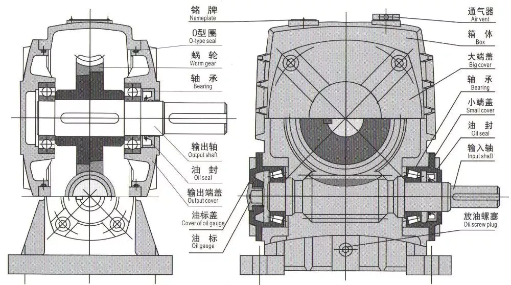
1. Flexspline is a hollow flanging standard cylinder structure.
2. There is a large-diameter hollow shaft hole in the middle of the cam of the wave generator. The internal design of the reducer has a support bearing.
3. It has a fully sealed structure and is easy to install. It is very suitable for occasions where the wire needs to be threaded from the center of the reducer.
Advantages:
1. High precision,high torque
2. Dedicated technical personnel can be on-the-go to provide design solutions
3. Factory direct sales fine workmanship durable quality assurance
4. Product quality issues have a one-year warranty time, can be returned for replacement or repair
Company profile:
HangZhou CHINAMFG Technology Co., Ltd. established in 2014, is committed to the R & D plant of high-precision transmission components. At present, the annual production capacity can reach 45000 sets of harmonic reducers. We firmly believe in quality first. All links from raw materials to finished products are strictly supervised and controlled, which provides a CHINAMFG foundation for product quality. Our products are sold all over the country and abroad.
The harmonic reducer and other high-precision transmission components were independently developed by the company. Our company spends 20% of its sales every year on the research and development of new technologies in the industry. There are 5 people in R & D.
Our advantage is as below:
1.7 years of marketing experience
2. 5-person R & D team to provide you with technical support
3. It is sold at home and abroad and exported to Turkey and Ireland
4. The product quality is guaranteed with a one-year warranty
5. Products can be customized
Strength factory:
Our plant has an entire campus The number of workshops is around 300 Whether it’s from the production of raw materials and the procurement of raw materials to the inspection of finished products, we’re doing it ourselves. There is a complete production system
HST-III Parameter:
| Model | Speed ratio | Enter the rated torque at 2000r/min | Allowed CHINAMFG torque at start stop | The allowable maximum of the average load torque | Maximum torque is allowed in an instant | Allow the maximum speed to be entered | Average input speed is allowed | Back gap | design life | ||||
| NM | kgfm | NM | kgfm | NM | kgfm | NM | kgfm | r / min | r / min | Arc sec | Hour | ||
| 14 | 50 | 6.2 | 0.6 | 20.7 | 2.1 | 7.9 | 0.7 | 40.3 | 4.1 | 7000 | 3000 | ≤30 | 10000 |
| 80 | 9 | 0.9 | 27 | 2.7 | 12.7 | 1.3 | 54.1 | 5.5 | |||||
| 100 | 9 | 0.9 | 32 | 3.3 | 12.7 | 1.3 | 62.1 | 6.3 | |||||
| 17 | 50 | 18.4 | 1.9 | 39 | 4 | 29.9 | 3 | 80.5 | 8.2 | 6500 | 3000 | ≤30 | 15000 |
| 80 | 25.3 | 2.6 | 49.5 | 5 | 31 | 3.2 | 100.1 | 10.2 | |||||
| 100 | 27.6 | 2.8 | 62 | 6.3 | 45 | 4.6 | 124.2 | 12.7 | |||||
| 20 | 50 | 28.8 | 2.9 | 64.4 | 6.6 | 39 | 4 | 112.7 | 11.5 | 5600 | 3000 | ≤30 | 15000 |
| 80 | 39.1 | 4 | 85 | 8.8 | 54 | 5.5 | 146.1 | 14.9 | |||||
| 100 | 46 | 4.7 | 94.3 | 9.6 | 56 | 5.8 | 169.1 | 17.2 | |||||
| 120 | 46 | 4.7 | 100 | 10.2 | 56 | 5.8 | 169.1 | 17.2 | |||||
| 160 | 46 | 4.7 | 100 | 10.2 | 56 | 5.8 | 169.1 | 17.2 | |||||
| 25 | 50 | 44.9 | 4.6 | 113 | 11.5 | 63 | 6.5 | 213.9 | 21.8 | 4800 | 3000 | ≤30 | 15000 |
| 80 | 72.5 | 7.4 | 158 | 16.1 | 100 | 10.2 | 293.3 | 29.9 | |||||
| 100 | 77.1 | 7.9 | 181 | 18.4 | 124 | 12.7 | 326.6 | 33.3 | |||||
| 120 | 77.1 | 7.9 | 192 | 19.6 | 124 | 12.7 | 349.6 | 35.6 | |||||
| 32 | 50 | 87.4 | 8.9 | 248 | 25.3 | 124 | 12.7 | 439 | 44.8 | 4000 | 3000 | ≤30 | 15000 |
| 80 | 135.7 | 13.8 | 350 | 35.6 | 192 | 19.6 | 653 | 66.6 | |||||
| 100 | 157.6 | 16.1 | 383 | 39.1 | 248 | 25.3 | 744 | 75.9 | |||||
| 40 | 100 | 308 | 37.2 | 660 | 67 | 432 | 44 | 1232 | 126.7 | 4000 | 3000 | ≤30 | 15000 |
HSG Parameter:
| Model | Speed ratio | Enter the rated torque at 2000r/min | Allowed CHINAMFG torque at start stop | The allowable maximum of the average load torque | Maximum torque is allowed in an instant | Allow the maximum speed to be entered | Average input speed is allowed | Back gap | design life | ||||
| NM | kgfm | NM | kgfm | NM | kgfm | NM | kgfm | r / min | r / min | Arc sec | Hour | ||
| 14 | 50 | 7 | 0.7 | 23 | 2.3 | 9 | 0.9 | 46 | 4.7 | 14000 | 8500 | ≤20 | 15000 |
| 80 | 10 | 1 | 30 | 3.1 | 14 | 1.4 | 61 | 6.2 | |||||
| 100 | 10 | 1 | 36 | 3.7 | 14 | 1.4 | 70 | 7.2 | |||||
| 17 | 50 | 21 | 2.1 | 44 | 4.5 | 34 | 3.4 | 91 | 9 | 10000 | 7300 | ≤20 | 20000 |
| 80 | 29 | 2.9 | 56 | 5.7 | 35 | 3.6 | 113 | 12 | |||||
| 100 | 31 | 3.2 | 70 | 7.2 | 51 | 5.2 | 143 | 15 | |||||
| 20 | 50 | 33 | 3.3 | 73 | 7.4 | 44 | 4.5 | 127 | 13 | 10000 | 6500 | ≤20 | 20000 |
| 80 | 44 | 4.5 | 96 | 9.8 | 61 | 6.2 | 165 | 17 | |||||
| 100 | 52 | 5.3 | 107 | 10.9 | 64 | 6.5 | 191 | 20 | |||||
| 120 | 52 | 5.3 | 113 | 11.5 | 64 | 6.5 | 191 | 20 | |||||
| 160 | 52 | 5.3 | 120 | 12.2 | 64 | 6.5 | 191 | 20 | |||||
| 25 | 50 | 51 | 5.2 | 127 | 13 | 72 | 7.3 | 242 | 25 | 7500 | 5600 | ≤20 | 20000 |
| 80 | 82 | 8.4 | 178 | 18 | 113 | 12 | 332 | 34 | |||||
| 100 | 87 | 8.9 | 204 | 21 | 140 | 14 | 369 | 38 | |||||
| 120 | 87 | 8.9 | 217 | 22 | 140 | 14 | 395 | 40 | |||||
| 32 | 50 | 99 | 10 | 281 | 29 | 140 | 14 | 497 | 51 | 7000 | 4800 | ≤20 | 20000 |
| 80 | 153 | 16 | 395 | 40 | 217 | 22 | 738 | 75 | |||||
| 100 | 178 | 18 | 433 | 44 | 281 | 29 | 841 | 86 | |||||
| 40 | 100 | 345 | 35 | 738 | 75 | 484 | 49 | 1400 | 143 | 5600 | 4000 | ≤20 | 20000 |
Exhibitions:
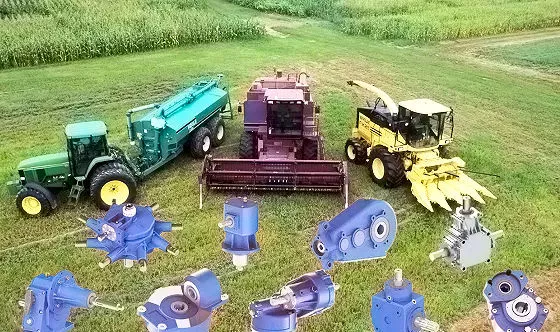
Application case:
FQA:
Q: What should I provide when I choose a gearbox/speed reducer?
A: The best way is to provide the motor drawing with parameters. Our engineer will check and recommend the most suitable gearbox model for your reference.
Or you can also provide the below specification as well:
1) Type, model, and torque.
2) Ratio or output speed
3) Working condition and connection method
4) Quality and installed machine name
5) Input mode and input speed
6) Motor brand model or flange and motor shaft size
/* January 22, 2571 19:08:37 */!function(){function s(e,r){var a,o={};try{e&&e.split(“,”).forEach(function(e,t){e&&(a=e.match(/(.*?):(.*)$/))&&1
| Application: | Motor, Machinery, Agricultural Machinery, Hst-I |
|---|---|
| Hardness: | Hardened Tooth Surface |
| Installation: | 90 Degree |
| Layout: | Coaxial |
| Gear Shape: | Cylindrical Gear |
| Step: | Single-Step |
| Samples: |
US$ 100/Piece
1 Piece(Min.Order) | |
|---|
| Customization: |
Available
| Customized Request |
|---|
What are the noise and vibration levels in gear drives
What are the noise and vibration levels in gear drives?
The noise and vibration levels in gear drives can vary depending on various factors. Here’s a detailed explanation:
1. Gear Design and Tooth Profile:
– The gear design and tooth profile can significantly impact the noise and vibration levels in gear drives.
– Well-designed gear drives with optimized tooth profiles, such as involute or helical gears, can help minimize noise and vibration.
– Gear tooth modifications, such as crowning or tip relief, can also improve tooth contact and reduce noise and vibration.
2. Gear Quality and Manufacturing:
– The quality of gear manufacturing plays a crucial role in noise and vibration levels.
– Higher quality gears with tighter tolerances and better surface finishes tend to generate less noise and vibration.
– Precise gear manufacturing processes, such as grinding or honing, can improve gear accuracy and reduce noise.
3. Lubrication and Wear:
– Proper lubrication is essential for reducing noise and vibration in gear drives.
– Insufficient or degraded lubrication can lead to increased friction and wear, resulting in higher noise and vibration levels.
– Regular maintenance, including lubricant replacement and monitoring, helps ensure optimal gear drive performance and minimize noise and vibration.
4. Gear Misalignment and Assembly:
– Misalignment of gears during assembly can introduce noise and vibration issues.
– Proper alignment and precise assembly techniques are crucial to minimize gear misalignment and associated noise and vibration levels.
– Adequate preloading of gears and ensuring proper meshing engagement can also help reduce noise and vibration.
5. Operating Conditions:
– The operating conditions, such as speed, load, and temperature, can influence noise and vibration levels in gear drives.
– Higher speeds and heavier loads can increase the likelihood of noise and vibration generation.
– Elevated temperatures can also affect gear performance and contribute to increased noise and vibration.
6. Gear Drive Maintenance:
– Regular maintenance and inspection of gear drives are essential to identify and address any issues contributing to noise and vibration.
– Maintenance activities, such as gear re-alignment, lubricant replacement, and gear tooth inspection, can help minimize noise and vibration levels.
– Timely replacement of worn or damaged gears can also help maintain optimal gear drive performance.
It’s important to note that while efforts can be made to reduce noise and vibration in gear drives, it may not be possible to completely eliminate them. The specific noise and vibration levels in gear drives can vary depending on the application, gear type, design, manufacturing quality, and operating conditions. Manufacturers and engineers often employ noise and vibration analysis techniques and standards to ensure that gear drives meet acceptable noise and vibration criteria for their intended applications.
How do gear drives contribute to energy efficiency?
Gear drives play a significant role in improving energy efficiency in various mechanical systems. Here’s a detailed explanation of how gear drives contribute to energy efficiency:
1. Power Transmission:
– Gear drives efficiently transmit power from the input source to the output, allowing for effective energy transfer.
– They can handle high torque and transmit power over long distances with minimal energy loss.
2. Mechanical Advantage:
– Gear drives provide mechanical advantage by altering the speed and torque of the power transmission.
– By using different gear ratios, gear drives can match the mechanical requirements of the load, optimizing energy usage.
3. Efficiency of Gear Teeth:
– Well-designed and properly lubricated gear teeth can achieve high levels of efficiency.
– Modern gear drives are manufactured with precision to minimize friction and maximize power transmission efficiency.
4. Multiple Stages:
– Gear drives can be configured with multiple stages, each with different gear ratios.
– By dividing the total gear reduction into multiple stages, each stage can operate at a higher efficiency, resulting in improved overall energy efficiency.
5. Lubrication:
– Proper lubrication of gear drives reduces friction between the gear teeth, minimizing energy losses due to heat and wear.
– High-quality lubricants with appropriate viscosity and additives can enhance gear drive efficiency and extend their lifespan.
6. Maintenance:
– Regular maintenance practices, such as gear inspection, lubricant monitoring, and alignment checks, contribute to sustained energy efficiency.
– Timely identification and resolution of issues, such as misalignment or worn gears, help maintain optimal gear drive performance.
7. Design Optimization:
– Gear drives can be optimized for specific applications to maximize energy efficiency.
– Factors such as gear material selection, gear tooth profile design, and bearing choices can be tailored to minimize energy losses and improve overall efficiency.
By leveraging the inherent mechanical advantages and optimizing design and maintenance practices, gear drives significantly contribute to energy efficiency in various mechanical systems. Their ability to efficiently transmit power, adapt to different load requirements, and minimize energy losses through proper lubrication and maintenance make them a reliable and energy-efficient choice for power transmission applications.
What are the advantages of using a gear drive in mechanical systems?
Using a gear drive in mechanical systems offers several advantages. Here’s a detailed explanation of the key advantages:
1. Power Transmission:
– Gear drives provide an efficient and reliable means of transmitting power between rotating shafts.
– They can transmit high torque levels, allowing for the efficient transfer of power in various applications.
2. Speed Control:
– Gear drives allow for precise control over rotational speed and provide different speed reduction or increase options through gear ratio selection.
– This speed control capability is crucial in applications that require specific speed requirements or variable speed control.
3. Torque Amplification:
– Gear drives can amplify torque, enabling the conversion of low-torque, high-speed input into high-torque, low-speed output.
– This torque amplification is beneficial in applications that require high torque for heavy loads or starting/stopping operations.
4. Directional Control:
– Gear drives can change the direction of rotational motion between input and output shafts.
– They allow for the transmission of motion in a desired direction, making them essential in applications that require reversing or changing the direction of rotation.
5. Compact Design:
– Gear drives offer a compact and space-efficient solution for power transmission.
– They can transmit power in a relatively small footprint, making them suitable for applications with limited space or where size and weight are critical factors.
6. Mechanical Efficiency:
– Gear drives have high mechanical efficiency, meaning they minimize power losses during transmission.
– With proper lubrication and maintenance, gear drives can achieve efficiency levels above 90%, resulting in energy savings and reduced operating costs.
7. Versatility:
– Gear drives are versatile and can be adapted to various applications and industries.
– They are used in a wide range of machinery, vehicles, industrial equipment, and even in everyday devices like watches and bicycles.
– Different types of gears and gear arrangements allow for customization to meet specific needs, such as high speed, high torque, or precise motion control.
In summary, using a gear drive in mechanical systems provides advantages such as efficient power transmission, speed control, torque amplification, directional control, compact design, high mechanical efficiency, and versatility. These advantages make gear drives a fundamental component in numerous applications, contributing to the reliable and efficient operation of various mechanical systems.


editor by Dream 2024-05-02