Product Description
Product Description
Product Description:
|
Model |
Socare SVD
|
Place of Origin |
HangZhou,China |
|
Brand |
Slewing Drive |
Delivery Time |
7 days |
|
Material |
42CrMo,50Mn |
Output Torque |
1.46kN.m |
|
Tilting Moment Torque |
13.5kN.m |
Holding Torque |
10.4kN.m |
|
Static Axial Rating |
133KN |
Static Radial Rating |
53KN |
|
Dynamic Axial Rating |
32KN |
Dynamic Radial Rating |
28 KN |
|
Gear Ratio |
71:1 |
Efficiency |
40% |
|
Hydraulic Motor |
Yes |
HS Code |
8483457190 |
Slewing Drive:
The title of Slewing Drive is no uniform, it also called: Slewing gear, rotary drive, rotary drive axle, rotary drive vice, slew drive, slewing gear, and rotary drive unit. At present the majority of such devices: The Slewing Drive.
In addition to the field of use in the daily solar power systems are usually used for Special vehicle, heavy-duty flat-panel truck, container cranes, truck mounted crane, automobile crane and aerial vehicles, cranes, gantry cranes, small wind power stations, space communications, satellite receiver, etc. . The Slewing Drive in the solar photovoltaic industry, the general configuration DC planetary reduction motor or AC geared motors; Main configuration of the hydraulic motor as a power-driven construction machinery.
Rotary speed reducer/slewing drive Main fetures:
1.large speed ratio range
2.small volume,low weight ,saving space for mounting.
3.high efficiency,high mechanical strength and high quality aluminum alloy housing
4.long life service,large output torque,low noise and little vibration
5.low temperature rise,omnibearing installation ,easy to connect with other machinery.
6.high carry ability,elegant apperance.
7.CE standard,input power can be 0.06KW-15KW
8.stable transmission
Socare Slewing Drives Features:
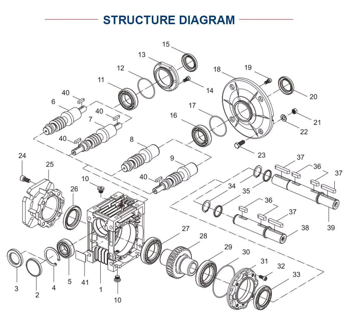
Socare Slewing drive is a special bearing. And a slewing drive usually consist of slewing bearing, worm shaft, housing, bearing, motor and so on.
Motor drive the worm shaft, the outer ring of slewing bearing will rotate, the outer ring output the torque through flange while the inner ring of slewing bearing is fixed in housing. Installation space savings advantages to a greater extent.
Application:
Slewing drives are widely used in aerospace area, solar power systems, wind turbines, satellite broadcasting system, and engineering machinery like truck cranes, and man lifts, etc. Recently years, it has been prosperously used in photovoltaic power generation systems, special vehicle, heavy-duty flat-panel truck, container cranes, truck mounted crane, automobile crane and aerial vehicles, cranes, gantry cranes, small wind power stations, space communications, satellite receiver, etc.
Our Advantages
Our Advantage:
1. Double skeleton oil seal structure, sealing performance reaches IP65, which can meet long-term outdoor use.
2. The surface of the slewing bearing adopts high-quality galvanized or QPQ treatment process, which has good corrosion resistance.
3. Worm gear meshing, high precision, large tooth contact area, high transmission torque, suitable for low speed and high torque applications.
4. Customized solutions to meet different application conditions.
Packaging & Shipping
/* January 22, 2571 19:08:37 */!function(){function s(e,r){var a,o={};try{e&&e.split(“,”).forEach(function(e,t){e&&(a=e.match(/(.*?):(.*)$/))&&1
| Application: | Motor, Electric Cars, Motorcycle, Machinery, Marine, Toy, Agricultural Machinery, Car |
|---|---|
| Hardness: | Hardened Tooth Surface |
| Installation: | Horizontal Type |
| Layout: | Expansion |
| Gear Shape: | Bevel Gear |
| Step: | Single-Step |
| Samples: |
US$ 500/Piece
1 Piece(Min.Order) | |
|---|
What safety precautions should be taken when working with gear drives?
Working with gear drives requires adherence to specific safety precautions to ensure the well-being of individuals involved. Here’s a detailed explanation:
1. Personal Protective Equipment (PPE):
– Wear appropriate personal protective equipment, such as safety glasses or goggles, gloves, and close-toed shoes, to protect against potential hazards.
– Use hearing protection if working in close proximity to gear drives that produce excessive noise.
2. Lockout/Tagout:
– Implement lockout/tagout procedures to isolate and de-energize gear drives before performing maintenance or repair tasks.
– This ensures that the equipment cannot be accidentally energized, preventing potential injury from unexpected movement or activation.
3. Training and Familiarity:
– Ensure that personnel working with gear drives are adequately trained and familiar with the equipment’s operation and safety procedures.
– Provide training on proper use, maintenance, and potential risks associated with gear drives.
4. Risk Assessment:
– Conduct a thorough risk assessment of the work area and gear drives to identify potential hazards and implement appropriate control measures.
– Address issues such as pinch points, entanglement hazards, and potential for falling objects.
5. Proper Installation and Maintenance:
– Follow manufacturer guidelines for the installation, setup, and maintenance of gear drives.
– Regularly inspect gears, shafts, bearings, and lubrication systems for signs of wear, damage, or malfunction.
– Perform maintenance tasks only when the gear drive is de-energized and properly locked out.
6. Guarding and Enclosures:
– Install appropriate guards and enclosures around gear drives to prevent accidental contact with moving parts.
– Ensure that guards are securely in place and not removed or bypassed during operation.
7. Proper Lifting and Handling:
– Use proper lifting techniques and equipment when moving or installing gear drives.
– Gear drives can be heavy and require mechanical means, such as cranes or forklifts, for safe handling.
8. Reporting and Addressing Safety Concerns:
– Encourage a culture of reporting and addressing safety concerns related to gear drives.
– Promptly address any identified safety issues or incidents to prevent future accidents.
It is essential to remember that these safety precautions serve as general guidelines, and specific precautions may vary depending on the type and size of the gear drives and the working environment. Always refer to the manufacturer’s instructions and consult with relevant safety professionals to ensure compliance with specific safety requirements.

How are gear drives used in renewable energy applications?
Gear drives play a crucial role in various renewable energy applications. Here’s a detailed explanation:
1. Wind Turbines:
– Gear drives are widely used in wind turbines to convert the low-speed rotation of the turbine blades into high-speed rotation suitable for generating electricity.
– The gear drives amplify the rotational speed, allowing the generator to operate at the required speed to produce electricity efficiently.
2. Solar Tracking Systems:
– In solar tracking systems, gear drives are employed to adjust the position of solar panels or mirrors to maximize the capture of solar energy.
– The gear drives enable precise and controlled movement of the panels or mirrors, aligning them with the sun’s position throughout the day for optimal energy collection.
3. Hydroelectric Power Plants:
– Gear drives are utilized in hydroelectric power plants to convert the slow rotational motion of the turbine into high-speed rotation for power generation.
– The gear drives increase the rotational speed and transmit the power to the generator, which converts the mechanical energy into electrical energy.
4. Tidal and Wave Energy Converters:
– Gear drives are employed in tidal and wave energy converters to increase the rotational speed of the turbine or generator system.
– They help convert the relatively slow and irregular motion of the tides or waves into a higher-speed rotation suitable for electricity generation.
5. Geothermal Power Plants:
– Gear drives are utilized in geothermal power plants to transmit power from the geothermal turbine to the generator for electricity production.
– They enable the conversion of the low-speed, high-torque rotational motion of the turbine into high-speed rotation required by the generator.
6. Biomass Energy Systems:
– Gear drives are used in biomass energy systems to convert the rotational motion of the biomass combustion engine or steam turbine into high-speed rotation for electricity generation.
– The gear drives help optimize the rotational speed and torque characteristics of the system for efficient power production.
Overall, gear drives are essential components in renewable energy applications, enabling the efficient conversion of various natural energy sources into usable electricity. They help amplify rotational speed, adjust positions for optimal energy capture, and transmit power from turbines to generators. By facilitating the effective utilization of renewable energy sources, gear drives contribute to the growth and sustainability of clean and renewable energy generation.
How do you calculate the gear ratio in a gear drive?
Calculating the gear ratio in a gear drive involves determining the relationship between the number of teeth on the driving gear (pinion) and the number of teeth on the driven gear. Here’s a detailed explanation:
The gear ratio is defined as the ratio of the number of teeth on the driven gear to the number of teeth on the driving gear. It represents the speed or torque multiplication or reduction achieved by the gear drive.
The gear ratio (GR) can be calculated using the following formula:
GR = Number of teeth on driven gear / Number of teeth on driving gear
For example, consider a gear drive with a driving gear (pinion) having 20 teeth and a driven gear having 60 teeth. The gear ratio can be calculated as follows:
GR = 60 (driven gear) / 20 (driving gear) = 3
In this case, the gear ratio is 3:1, indicating that for every three revolutions of the driving gear, the driven gear completes one revolution. This represents a speed reduction, with the driven gear rotating at one-third the speed of the driving gear.
It’s important to note that the gear ratio can be expressed in different formats, such as a decimal, fraction, or as a ratio. The choice of representation depends on the specific requirements and conventions of the gear drive application.
Additionally, it’s worth mentioning that gear drives can have multiple gears arranged in series or parallel, forming gear trains. In such cases, the overall gear ratio is calculated by multiplying the individual gear ratios of each gear pair in the train.
When designing or selecting gear drives, calculating the gear ratio is essential for determining the speed reduction or increase and torque amplification provided by the gear system. It enables engineers and designers to match the gear drive to the desired operational requirements of the mechanical system.


editor by Dream 2024-04-30