Product Description
Product Description:
1. Flexspline is a hollow flanging standard cylinder structure.
2. The structure of the whole item is compact. The input shaft is directly matched with the inner hole of the wave generator. They are connected by a flat key slot.
3. The connecting way is circular spline fixed and flexible output, Or it can also be used that flexible fixed and circular spline output.
Advantages:
1. High precision, high torque
2. Dedicated technical personnel can be on-the-go to provide design solutions
3. Factory direct sales fine workmanship durable quality assurance
4. Product quality issues have a one-year warranty time, can be returned for replacement or repair
Company profile:
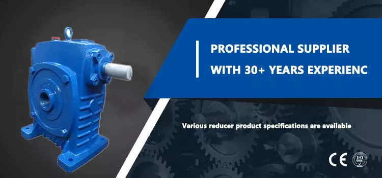
HangZhou CHINAMFG Technology Co., Ltd. established in 2014, is committed to the R & D plant of high-precision transmission components. At present, the annual production capacity can reach 45000 sets of harmonic reducers. We firmly believe in quality first. All links from raw materials to finished products are strictly supervised and controlled, which provides a CHINAMFG foundation for product quality. Our products are sold all over the country and abroad.
The harmonic reducer and other high-precision transmission components were independently developed by the company. Our company spends 20% of its sales every year on the research and development of new technologies in the industry. There are 5 people in R & D.
Our advantage is as below:
1.7 years of marketing experience
2. 5-person R & D team to provide you with technical support
3. It is sold at home and abroad and exported to Turkey and Ireland
4. The product quality is guaranteed with a one-year warranty
5. Products can be customized
Strength factory:
Our plant has an entire campus The number of workshops is around 300 Whether it’s from the production of raw materials and the procurement of raw materials to the inspection of finished products, we’re doing it ourselves. There is a complete production system
HCS-I Parameter:
| Model | Speed ratio | Enter the rated torque at 2000r/min | Allowed CHINAMFG torque at start stop | The allowable maximum of the average load torque | Maximum torque is allowed in an instant | Allow the maximum speed to be entered | Average input speed is allowed | Back gap | design life | ||||
| NM | kgfm | NM | kgfm | NM | kgfm | NM | kgfm | r / min | r / min | Arc sec | Hour | ||
| 11 | 80 | 3.8 | 0.4 | 8.5 | 0.9 | 6.8 | 0.7 | 19.1 | 1.9 | 8000 | 3000 | ≤30 | 10000 |
| 100 | 4.1 | 0.4 | 8.9 | 0.9 | 7.2 | 0.7 | 20 | 2 | |||||
| 14 | 50 | 6.2 | 0.6 | 20.7 | 2.1 | 7.9 | 0.7 | 40.3 | 4.1 | 7000 | 3000 | ≤30 | 15000 |
| 80 | 9 | 0.9 | 27 | 2.7 | 12.7 | 1.3 | 54.1 | 5.5 | |||||
| 100 | 9 | 0.9 | 32 | 3.3 | 12.7 | 1.3 | 62.1 | 6.3 | |||||
| 17 | 50 | 18.4 | 1.9 | 39 | 4 | 29.9 | 3 | 80.5 | 8.2 | 6500 | 3000 | ≤30 | 15000 |
| 80 | 25.3 | 2.6 | 49.5 | 5 | 31 | 3.2 | 100.1 | 10.2 | |||||
| 100 | 27.6 | 2.8 | 62 | 6.3 | 45 | 4.6 | 124.2 | 12.7 | |||||
| 20 | 50 | 28.8 | 2.9 | 64.4 | 6.6 | 39 | 4 | 112.7 | 11.5 | 5600 | 3000 | ≤30 | 15000 |
| 80 | 39.1 | 4 | 85 | 8.8 | 54 | 5.5 | 146.1 | 14.9 | |||||
| 100 | 46 | 4.7 | 94.3 | 9.6 | 56 | 5.8 | 169.1 | 17.2 | |||||
| 120 | 46 | 4.7 | 100 | 10.2 | 56 | 5.8 | 169.1 | 17.2 | |||||
| 160 | 46 | 4.7 | 112 | 10.9 | 56 | 5.8 | 169.1 | 17.2 | |||||
| 25 | 50 | 44.9 | 4.6 | 113 | 11.5 | 63 | 6.5 | 213.9 | 21.8 | 4800 | 3000 | ≤30 | 15000 |
| 80 | 72.5 | 7.4 | 158 | 16.1 | 100 | 10.2 | 293.3 | 29.9 | |||||
| 100 | 77.1 | 7.9 | 181 | 18.4 | 124 | 12.7 | 326.6 | 33.3 | |||||
| 120 | 77.1 | 7.9 | 192 | 19.6 | 124 | 12.7 | 349.6 | 35.6 | |||||
| 32 | 50 | 87.4 | 8.9 | 248 | 25.3 | 124 | 12.7 | 439 | 44.8 | 4000 | 3000 | ≤30 | 15000 |
| 80 | 135.7 | 13.8 | 350 | 35.6 | 192 | 19.6 | 653 | 66.6 | |||||
| 100 | 157.6 | 16.1 | 383 | 39.1 | 248 | 25.3 | 744 | 75.9 | |||||
| 120 | 157.6 | 16.1 | 406 | 41.4 | 248 | 25.3 | 789 | 80.5 | |||||
HCG Parameter:
| Model | Speed ratio | Enter the rated torque at 2000r/min | Allowed CHINAMFG torque at start stop | The allowable maximum of the average load torque | Maximum torque is allowed in an instant | Allow the maximum speed to be entered | Average input speed is allowed | Back gap | design life | ||||
| NM | kgfm | NM | kgfm | NM | kgfm | NM | kgfm | r / min | r / min | Arc sec | Hour | ||
| 11 | 80 | 3.8 | 0.4 | 8.5 | 0.9 | 6.8 | 0.7 | 19.1 | 1.9 | 8000 | 3000 | ≤20 | 10000 |
| 100 | 4.1 | 0.4 | 8.9 | 0.9 | 7.2 | 0.7 | 20 | 2 | |||||
| 14 | 50 | 7 | 0.7 | 23 | 2.3 | 9 | 0.9 | 46 | 4.7 | 10000 | 6500 | ≤20 | 15000 |
| 80 | 10 | 1 | 30 | 3.1 | 14 | 1.4 | 61 | 6.2 | |||||
| 100 | 10 | 1 | 36 | 3.7 | 14 | 1.4 | 70 | 7.2 | |||||
| 17 | 50 | 21 | 2.1 | 44 | 4.5 | 34 | 3.4 | 91 | 9 | 7500 | 5600 | ≤20 | 20000 |
| 80 | 29 | 2.9 | 56 | 5.7 | 35 | 3.6 | 113 | 12 | |||||
| 100 | 31 | 3.2 | 70 | 7.2 | 51 | 5.2 | 143 | 15 | |||||
| 20 | 50 | 33 | 3.3 | 73 | 7.4 | 44 | 4.5 | 127 | 13 | 7000 | 4800 | ≤20 | 2000 |
| 80 | 44 | 4.5 | 96 | 9.8 | 61 | 6.2 | 165 | 17 | |||||
| 100 | 52 | 5.3 | 107 | 10.9 | 64 | 6.5 | 191 | 20 | |||||
| 120 | 52 | 5.3 | 113 | 11.5 | 64 | 6.5 | 191 | 20 | |||||
| 160 | 52 | 5.3 | 120 | 12.2 | 64 | 6.5 | 191 | 20 | |||||
| 25 | 50 | 51 | 5.2 | 127 | 13 | 72 | 7.3 | 242 | 25 | 5600 | 4000 | ≤20 | 2000 |
| 80 | 82 | 8.4 | 178 | 18 | 113 | 12 | 332 | 34 | |||||
| 100 | 87 | 8.9 | 204 | 21 | 140 | 14 | 369 | 38 | |||||
| 120 | 87 | 8.9 | 217 | 22 | 140 | 14 | 395 | 40 | |||||
| 32 | 50 | 99 | 10 | 281 | 29 | 140 | 14 | 497 | 51 | 5600 | 3000 | ≤20 | 2000 |
| 80 | 153 | 16 | 395 | 40 | 217 | 22 | 738 | 75 | |||||
| 100 | 178 | 18 | 433 | 44 | 281 | 29 | 841 | 86 | |||||
| 120 | 178 | 18 | 459 | 47 | 281 | 29 | 892 | 91 | |||||
Exhibitions:
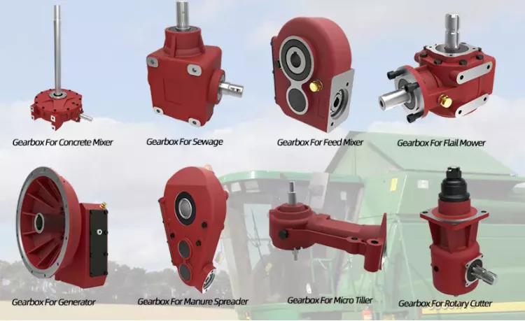
Application case:
FQA:
Q: What should I provide when I choose a gearbox/speed reducer?
A: The best way is to provide the motor drawing with parameters. Our engineer will check and recommend the most suitable gearbox model for your reference.
Or you can also provide the below specification as well:
1) Type, model, and torque.
2) Ratio or output speed
3) Working condition and connection method
4) Quality and installed machine name
5) Input mode and input speed
6) Motor brand model or flange and motor shaft size
/* January 22, 2571 19:08:37 */!function(){function s(e,r){var a,o={};try{e&&e.split(“,”).forEach(function(e,t){e&&(a=e.match(/(.*?):(.*)$/))&&1
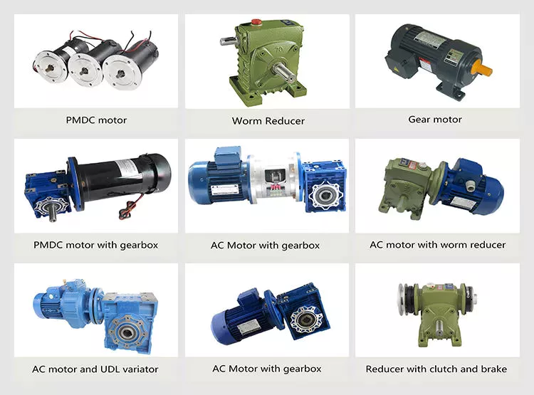
| Application: | Motor, Electric Cars, Motorcycle, Machinery, Marine, Car |
|---|---|
| Hardness: | Hardened Tooth Surface |
| Installation: | 90 Degree |
| Layout: | Coaxial |
| Gear Shape: | Cylindrical Gear |
| Step: | Single-Step |
| Customization: |
Available
| Customized Request |
|---|
How do gear drives work in robotic and automated systems?
Gear drives play a crucial role in robotic and automated systems by transmitting motion and power between different components. Here’s a detailed explanation of how gear drives work in these systems:
1. Power Transmission:
– In robotic and automated systems, gear drives are used to transmit power from motors to various mechanical components.
– Electric motors provide rotational motion, which is converted into linear or angular motion by the gear drive.
– The gear drive consists of a set of gears with different sizes and configurations that mesh together to transfer torque and speed.
2. Speed and Torque Conversion:
– Gear drives allow for the conversion of speed and torque between the motor and the driven components.
– By using gears with different sizes (varying number of teeth), the gear drive can change the rotational speed and torque output.
– For example, a gear drive with a larger gear driving a smaller gear will increase the torque while reducing the speed, and vice versa.
3. Motion Control:
– Gear drives enable precise motion control in robotic and automated systems.
– By selecting the appropriate gear ratio, the gear drive can control the speed and position of the driven components.
– Gear drives can be used to achieve smooth and accurate movements, such as in robot arms, conveyor systems, or CNC machines.
4. Reducing Inertia:
– Inertia refers to an object’s resistance to changes in motion.
– Gear drives can help reduce the overall inertia in robotic and automated systems.
– By using smaller gears, the gear drive can reduce the inertia of the driven components, allowing for faster and more responsive movements.
5. Backlash Compensation:
– Backlash refers to the slight play or clearance between gear teeth, which can result in a loss of accuracy and precision.
– Gear drives in robotic and automated systems often incorporate backlash compensation mechanisms to minimize this issue.
– These mechanisms can include preloading the gears or using anti-backlash gears to eliminate or reduce the effects of backlash.
6. Load Distribution:
– In complex robotic systems, multiple gear drives are often used to distribute the load and share the torque among different components.
– This distribution of load helps prevent overloading of individual gear drives and ensures a balanced operation of the system.
7. Redundancy:
– Some robotic and automated systems incorporate redundant gear drives to enhance reliability and fault tolerance.
– Redundant gear drives can provide backup functionality in case of failure or allow for continued operation with reduced performance in the event of a single gear drive failure.
Overall, gear drives are essential components in robotic and automated systems, enabling power transmission, motion control, speed and torque conversion, and load distribution. The specific design and configuration of gear drives in these systems depend on the application requirements, desired performance, and system constraints.
What are the signs of wear and tear in gear drives?
Identifying signs of wear and tear in gear drives is crucial for timely maintenance and preventing further damage. Here’s a detailed explanation of the common signs indicating wear and tear in gear drives:
1. Abnormal Noise:
– Unusual or increased noise during gear drive operation, such as grinding, squealing, or knocking sounds, can indicate worn or damaged gears.
– Excessive noise may result from pitting, chipping, or misalignment of gear teeth, requiring immediate attention.
2. Vibration:
– Excessive vibration during gear drive operation can be a sign of misalignment, gear tooth wear, or bearing damage.
– Vibrations may cause additional stress on the gears and other components, leading to accelerated wear and potential failure.
3. Changes in Performance:
– Decreased efficiency, reduced power transmission, or changes in speed and torque output can indicate wear and tear in gear drives.
– Increased slippage or difficulty in engaging gears may be a result of worn gear teeth or insufficient lubrication.
4. Increased Operating Temperature:
– If the gear drive operates at a higher temperature than normal, it could indicate excessive friction due to wear or inadequate lubrication.
– Elevated temperatures can accelerate wear and affect the overall performance and lifespan of the gear drive.
5. Oil Analysis:
– Regular oil analysis can help identify wear particles, contaminants, and changes in lubricant properties that indicate gear drive wear and tear.
– Presence of metal shavings, discoloration, or unusual debris in the oil can suggest gear or bearing deterioration.
6. Visual Inspection:
– Visually inspect the gear teeth for signs of pitting, chipping, scoring, or uneven wear patterns.
– Check for signs of excessive backlash, misalignment, or damage to bearings, shafts, and seals.
– Any visible damage or irregularities indicate wear and tear that requires attention.
7. Increased Friction:
– Higher friction levels, resulting in increased energy consumption or overheating, can be indicative of worn gears or inadequate lubrication.
– Excessive friction can lead to accelerated wear and further damage to the gear drive components.
It is important to address these signs of wear and tear promptly to prevent further deterioration and potential failure of the gear drive. Regular inspection, maintenance, and lubrication practices can help identify and mitigate wear-related issues, ensuring optimal performance and longevity of the gear drive system.
What are the different types of gear drives available?
There are several types of gear drives available, each suited for specific applications and requirements. Here’s a detailed explanation of some common types of gear drives:
1. Spur Gear Drive:
– Spur gear drives are the simplest and most common type of gear drives.
– They consist of cylindrical gears with straight teeth that are parallel to the gear axis.
– Spur gears provide high efficiency and are suitable for applications with low to moderate speeds and torque.
2. Helical Gear Drive:
– Helical gear drives have angled teeth that are inclined to the gear axis.
– The helical teeth allow for smooth and quiet operation, as they gradually engage and disengage.
– Helical gear drives can handle higher loads and speeds compared to spur gears and are commonly used in automotive transmissions and industrial machinery.
3. Bevel Gear Drive:
– Bevel gear drives consist of gears with conical-shaped teeth.
– They are used when the input and output shafts are not parallel but intersecting at an angle.
– Bevel gear drives are commonly found in applications such as differential gears in vehicles and power transmission systems for right-angle drives.
4. Worm Gear Drive:
– Worm gear drives consist of a threaded gear (worm) and a mating gear (worm wheel).
– They provide high gear ratios and are used when large speed reductions are required.
– Worm gear drives offer self-locking characteristics, meaning they can hold the load in position without the need for additional braking mechanisms.
5. Planetary Gear Drive:
– Planetary gear drives consist of multiple gears arranged in a planetary system.
– They offer high torque capacity, compact size, and versatility in speed and torque combinations.
– Planetary gear drives are commonly used in robotics, automotive transmissions, and industrial machinery.
6. Rack and Pinion Drive:
– Rack and pinion drives convert rotational motion into linear motion.
– They consist of a straight toothed rack (a flat gear) and a pinion (a gear with a small diameter).
– Rack and pinion drives are commonly used in applications such as steering systems, CNC machines, and linear actuators.
These are just a few examples of the different types of gear drives available. Each type has its advantages and is suitable for specific applications based on factors such as load capacity, speed requirements, space limitations, and desired gear ratios.


editor by Dream 2024-05-02