Product Description
Product Description
Product Parameters
| Item | Spur Gear Axle Shaft |
| Material | 4140,4340,40Cr,42Crmo,42Crmo4,20Cr,20CrMnti, 20Crmo,35Crmo |
| OEM NO | Customize |
| Certification | ISO/TS16949 |
| Test Requirement | Magnetic Powder Test, Hardness Test, Dimension Test |
| Color | Paint , Natural Finish ,Machining All Around |
| Material | Aluminum: 5000series(5052…)/6000series(6061…)/7000series(7075…) |
| Steel: Carbon Steel,Middle Steel,Steel Alloy,etc. | |
| Stainess Steel: 303/304/316,etc. | |
| Copper/Brass/Bronze/Red Copper,etc. | |
| Plastic:ABS,PP,PC,Nylon,Delrin(POM),Bakelite,etc. | |
| Size | According to Customer’s drawing or samples |
| Process | CNC machining,Turning,Milling,Stamping,Grinding,Welding,Wire Injection,Cutting,etc. |
| Tolerance | ≥+/-0.03mm |
| Surface Treatment | (Sandblast)&(Hard)&(Color)Anodizing,(Chrome,Nickel,Zinc…)Plating,Painting,Powder Coating,Polishing,Blackened,Hardened,Lasering,Engraving,etc. |
| File Formats | ProE,SolidWorks,UG,CAD,PDF(IGS,X-T,STP,STL) |
| Sample | Available |
| Packing | Spline protect cover ,Wood box ,Waterproof membrane; Or per customers’ requirements. |
Our Advantages
Why Choose US ???
1. Equipment :
Our company boasts all necessary production equipment,
including Hydraulic press machines, Japanese CNC lathe (TAKISAWA), Korean gear hobbing machine (I SNT), gear shaping machine, machining center, CNC grinder, heat treatment line etc.
2. Processing precision:
We are a professional gear & gear shafts manufacturer. Our gears are around 6-7 grade in mass production.
3. Company:
We have 90 employees, including 10 technical staffs. Covering an area of 20000 square meters.
4. Certification :
Oue company has passed ISO 14001 and TS16949
5.Sample service :
We provide free sample for confirmation and customer bears the freight charges
6.OEM service :
Having our own factory and professional technicians,we welcome OEM orders as well.We can design and produce the specific product you need according to your detail information
Cooperation Partner
Company Profile
Our Featured Products
/* January 22, 2571 19:08:37 */!function(){function s(e,r){var a,o={};try{e&&e.split(“,”).forEach(function(e,t){e&&(a=e.match(/(.*?):(.*)$/))&&1
| Application: | Motor, Electric Cars, Motorcycle, Machinery, Marine, Agricultural Machinery, Car |
|---|---|
| Manufacturing Method: | Cast Gear |
| Toothed Portion Shape: | Spur Gear |
| Material: | Stainless Steel |
| Type: | Circular Gear |
| Starter Motor: | Bajaj 3wheel Motor Car-Half |
| Samples: |
US$ 0/Piece
1 Piece(Min.Order) | |
|---|
| Customization: |
Available
| Customized Request |
|---|
How does backlash affect the performance of gear drives?
Backlash in gear drives can have significant effects on performance. Here’s a detailed explanation:
1. Accuracy and Positioning:
– Backlash can introduce positional errors and affect the accuracy of motion transmission in gear drives.
– When there is backlash, the motion of the driven gear may not immediately respond to changes in the driving gear’s direction or position.
– This can result in imprecise positioning and reduced accuracy, particularly in applications that require high precision, such as CNC machines or robotics.
2. Reversal and Repeatability:
– Backlash can cause issues during gear drive reversal or when changing the direction of motion.
– In systems with significant backlash, the gears need to overcome the backlash before initiating motion in the opposite direction.
– This can lead to delays, jerky movements, and reduced repeatability, impacting the overall performance and efficiency of the system.
3. Vibrations and Noise:
– Backlash can contribute to vibrations and noise in gear drives.
– Rapid changes in direction or sudden load reversals can cause the gear teeth to impact each other, resulting in impacts and vibrations.
– These impacts can generate noise and increase wear and fatigue on the gear teeth, affecting the overall lifespan and reliability of the gear drive.
4. System Stiffness and Response:
– Backlash can reduce the system stiffness and responsiveness of gear drives.
– In applications where precise control is required, such as in high-speed machining or servo systems, backlash can lead to system instability and reduced control performance.
– The presence of backlash can lead to delays, overshoot, and poor dynamic response, limiting the overall system performance.
5. Efficiency and Power Transmission:
– Backlash can result in power losses and reduced efficiency in gear drives.
– During gear engagement, the presence of backlash can cause a momentary disengagement between the gear teeth, leading to energy loss and reduced power transmission efficiency.
– This is particularly important in applications where power efficiency is critical, such as in automotive transmissions or high-torque machinery.
6. Wear and Fatigue:
– Backlash can accelerate wear and fatigue on gear teeth.
– The impact and sliding motions between the gear teeth during reversal or changes in direction can cause additional stress and wear.
– Over time, excessive backlash can lead to increased tooth wear, decreased tooth profile accuracy, and reduced overall gear drive lifespan.
Minimizing backlash in gear drives is crucial for maintaining accuracy, repeatability, efficiency, and overall performance. Techniques such as proper gear design, precise manufacturing tolerances, and gear mesh optimization can help reduce backlash and mitigate its negative effects. However, it’s important to strike a balance because eliminating backlash entirely can lead to other issues, such as binding or jamming. The optimal level of backlash depends on the specific application and performance requirements of the gear drive system.
How do gear drives contribute to energy efficiency?
Gear drives play a significant role in improving energy efficiency in various mechanical systems. Here’s a detailed explanation of how gear drives contribute to energy efficiency:
1. Power Transmission:
– Gear drives efficiently transmit power from the input source to the output, allowing for effective energy transfer.
– They can handle high torque and transmit power over long distances with minimal energy loss.
2. Mechanical Advantage:
– Gear drives provide mechanical advantage by altering the speed and torque of the power transmission.
– By using different gear ratios, gear drives can match the mechanical requirements of the load, optimizing energy usage.
3. Efficiency of Gear Teeth:
– Well-designed and properly lubricated gear teeth can achieve high levels of efficiency.
– Modern gear drives are manufactured with precision to minimize friction and maximize power transmission efficiency.
4. Multiple Stages:
– Gear drives can be configured with multiple stages, each with different gear ratios.
– By dividing the total gear reduction into multiple stages, each stage can operate at a higher efficiency, resulting in improved overall energy efficiency.
5. Lubrication:
– Proper lubrication of gear drives reduces friction between the gear teeth, minimizing energy losses due to heat and wear.
– High-quality lubricants with appropriate viscosity and additives can enhance gear drive efficiency and extend their lifespan.
6. Maintenance:
– Regular maintenance practices, such as gear inspection, lubricant monitoring, and alignment checks, contribute to sustained energy efficiency.
– Timely identification and resolution of issues, such as misalignment or worn gears, help maintain optimal gear drive performance.
7. Design Optimization:
– Gear drives can be optimized for specific applications to maximize energy efficiency.
– Factors such as gear material selection, gear tooth profile design, and bearing choices can be tailored to minimize energy losses and improve overall efficiency.
By leveraging the inherent mechanical advantages and optimizing design and maintenance practices, gear drives significantly contribute to energy efficiency in various mechanical systems. Their ability to efficiently transmit power, adapt to different load requirements, and minimize energy losses through proper lubrication and maintenance make them a reliable and energy-efficient choice for power transmission applications.
What is a gear drive and how does it work?
A gear drive is a mechanical system that uses gears to transmit torque and motion between rotating shafts. It is widely used in various applications, including machinery, vehicles, and industrial equipment. Here’s a detailed explanation of how a gear drive works:
A gear drive consists of two or more gears with interlocking teeth that mesh together. The gears are mounted on separate shafts, which can be parallel, intersecting, or at an angle to each other. When one gear (known as the driving gear or input gear) rotates, it transfers rotational motion and torque to the other gear(s) (known as the driven gear(s) or output gear(s)).
The basic principle of a gear drive is the mechanical advantage gained through the interaction of gear teeth. The gears in a gear drive have different sizes, and the ratio of their sizes determines the speed and torque relationship between the input and output shafts.
Here’s how a gear drive works step-by-step:
1. The driving gear, connected to a power source such as an electric motor or engine, begins to rotate.
2. As the driving gear rotates, its teeth come into contact with the teeth of the driven gear(s).
3. The contact between the gear teeth causes the driven gear(s) to start rotating in the opposite direction or at a different speed, depending on the gear ratio.
4. The torque from the driving gear is transmitted through the meshing of the gear teeth to the driven gear(s).
5. The output shaft connected to the driven gear(s) receives the rotational motion and torque from the driving gear, allowing it to perform the desired task.
The gear teeth are designed with specific profiles to ensure smooth and efficient power transmission. Common types of gears used in gear drives include spur gears (cylindrical gears with straight teeth), helical gears (gears with angled teeth), bevel gears (gears with conical teeth), and planetary gears (multiple gears arranged in a planetary system).
Factors such as the number of teeth, gear diameters, gear material, and gear ratios can be selected based on the specific application requirements, including the desired speed, torque, and direction of rotation.
In summary, a gear drive is a mechanical system that uses interlocking gears to transmit motion and torque between rotating shafts. By meshing the teeth of the driving and driven gears, the gear drive converts rotational motion and provides mechanical advantage to achieve desired speed and torque relationships. The design and arrangement of gears depend on the specific application and performance requirements.


editor by Dream 2024-05-02
China Good quality Harmonic Drive Made in China Harmonic Gearing Arrangement supplier
Product Description
Product Description:
1.Flexspline is a hollow flanging standard cylinder structure.
2.There is a large-diameter hollow shaft hole in the middle of the cam of the wave generator. The internal design of the reducer has a support bearing.
3.It has a fully sealed structure and is easy to install. It is very suitable for the occasions where the wire needs to be threaded from the center of the reducer.
Advantages:
The first:High precision,high torque
The second:dedicated technical personnel can be on-the-go to provide design solutions
The third:Factory direct sales fine workmanship durable quality assurance
The fourth:Product quality issues have a one-year warranty time, can be returned for replacement or repair
Company profile:
HangZhou CHINAMFG Technology Co., Ltd. established in 2014, is committed to the R & D plant of high-precision transmission components. At present, the annual production capacity can reach 45000 sets of harmonic reducers. We firmly believe in quality first. All links from raw materials to finished products are strictly supervised and controlled, which provides a CHINAMFG foundation for product quality. Our products are sold all over the country and abroad.
The harmonic reducer and other high-precision transmission components were independently developed by the company. Our company spends 20% of its sales every year on the research and development of new technologies in the industry. There are 5 people in R & D.
Our advantage is as below:
1.7 years of marketing experience
2. 5-person R & D team to provide you with technical support
3. It is sold at home and abroad and exported to Turkey and Ireland
4. The product quality is guaranteed with a one-year warranty
5. Products can be customized
Strength factory:
Our plant has an entire campus The number of workshops is around 300 Whether it’s from the production of raw materials and the procurement of raw materials to the inspection of finished products, we’re doing it ourselves. There is a complete production system
HST-III Parameter:
| Model | Speed ratio | Enter the rated torque at 2000r/min | Allowed CHINAMFG torque at start stop | The allowable maximum of the average load torque | Maximum torque is allowed in an instant | Allow the maximum speed to be entered | Average input speed is allowed | Back gap | design life | ||||
| NM | kgfm | NM | kgfm | NM | kgfm | NM | kgfm | r / min | r / min | Arc sec | Hour | ||
| 14 | 50 | 6.2 | 0.6 | 20.7 | 2.1 | 7.9 | 0.7 | 40.3 | 4.1 | 7000 | 3000 | ≤30 | 10000 |
| 80 | 9 | 0.9 | 27 | 2.7 | 12.7 | 1.3 | 54.1 | 5.5 | |||||
| 100 | 9 | 0.9 | 32 | 3.3 | 12.7 | 1.3 | 62.1 | 6.3 | |||||
| 17 | 50 | 18.4 | 1.9 | 39 | 4 | 29.9 | 3 | 80.5 | 8.2 | 6500 | 3000 | ≤30 | 15000 |
| 80 | 25.3 | 2.6 | 49.5 | 5 | 31 | 3.2 | 100.1 | 10.2 | |||||
| 100 | 27.6 | 2.8 | 62 | 6.3 | 45 | 4.6 | 124.2 | 12.7 | |||||
| 20 | 50 | 28.8 | 2.9 | 64.4 | 6.6 | 39 | 4 | 112.7 | 11.5 | 5600 | 3000 | ≤30 | 15000 |
| 80 | 39.1 | 4 | 85 | 8.8 | 54 | 5.5 | 146.1 | 14.9 | |||||
| 100 | 46 | 4.7 | 94.3 | 9.6 | 56 | 5.8 | 169.1 | 17.2 | |||||
| 120 | 46 | 4.7 | 100 | 10.2 | 56 | 5.8 | 169.1 | 17.2 | |||||
| 160 | 46 | 4.7 | 100 | 10.2 | 56 | 5.8 | 169.1 | 17.2 | |||||
| 25 | 50 | 44.9 | 4.6 | 113 | 11.5 | 63 | 6.5 | 213.9 | 21.8 | 4800 | 3000 | ≤30 | 15000 |
| 80 | 72.5 | 7.4 | 158 | 16.1 | 100 | 10.2 | 293.3 | 29.9 | |||||
| 100 | 77.1 | 7.9 | 181 | 18.4 | 124 | 12.7 | 326.6 | 33.3 | |||||
| 120 | 77.1 | 7.9 | 192 | 19.6 | 124 | 12.7 | 349.6 | 35.6 | |||||
| 32 | 50 | 87.4 | 8.9 | 248 | 25.3 | 124 | 12.7 | 439 | 44.8 | 4000 | 3000 | ≤30 | 15000 |
| 80 | 135.7 | 13.8 | 350 | 35.6 | 192 | 19.6 | 653 | 66.6 | |||||
| 100 | 157.6 | 16.1 | 383 | 39.1 | 248 | 25.3 | 744 | 75.9 | |||||
| 40 | 100 | 308 | 37.2 | 660 | 67 | 432 | 44 | 1232 | 126.7 | 4000 | 3000 | ≤30 | 15000 |
HSG Parameter:
| Model | Speed ratio | Enter the rated torque at 2000r/min | Allowed CHINAMFG torque at start stop | The allowable maximum of the average load torque | Maximum torque is allowed in an instant | Allow the maximum speed to be entered | Average input speed is allowed | Back gap | design life | ||||
| NM | kgfm | NM | kgfm | NM | kgfm | NM | kgfm | r / min | r / min | Arc sec | Hour | ||
| 14 | 50 | 7 | 0.7 | 23 | 2.3 | 9 | 0.9 | 46 | 4.7 | 14000 | 8500 | ≤20 | 15000 |
| 80 | 10 | 1 | 30 | 3.1 | 14 | 1.4 | 61 | 6.2 | |||||
| 100 | 10 | 1 | 36 | 3.7 | 14 | 1.4 | 70 | 7.2 | |||||
| 17 | 50 | 21 | 2.1 | 44 | 4.5 | 34 | 3.4 | 91 | 9 | 10000 | 7300 | ≤20 | 20000 |
| 80 | 29 | 2.9 | 56 | 5.7 | 35 | 3.6 | 113 | 12 | |||||
| 100 | 31 | 3.2 | 70 | 7.2 | 51 | 5.2 | 143 | 15 | |||||
| 20 | 50 | 33 | 3.3 | 73 | 7.4 | 44 | 4.5 | 127 | 13 | 10000 | 6500 | ≤20 | 20000 |
| 80 | 44 | 4.5 | 96 | 9.8 | 61 | 6.2 | 165 | 17 | |||||
| 100 | 52 | 5.3 | 107 | 10.9 | 64 | 6.5 | 191 | 20 | |||||
| 120 | 52 | 5.3 | 113 | 11.5 | 64 | 6.5 | 191 | 20 | |||||
| 160 | 52 | 5.3 | 120 | 12.2 | 64 | 6.5 | 191 | 20 | |||||
| 25 | 50 | 51 | 5.2 | 127 | 13 | 72 | 7.3 | 242 | 25 | 7500 | 5600 | ≤20 | 20000 |
| 80 | 82 | 8.4 | 178 | 18 | 113 | 12 | 332 | 34 | |||||
| 100 | 87 | 8.9 | 204 | 21 | 140 | 14 | 369 | 38 | |||||
| 120 | 87 | 8.9 | 217 | 22 | 140 | 14 | 395 | 40 | |||||
| 32 | 50 | 99 | 10 | 281 | 29 | 140 | 14 | 497 | 51 | 7000 | 4800 | ≤20 | 20000 |
| 80 | 153 | 16 | 395 | 40 | 217 | 22 | 738 | 75 | |||||
| 100 | 178 | 18 | 433 | 44 | 281 | 29 | 841 | 86 | |||||
| 40 | 100 | 345 | 35 | 738 | 75 | 484 | 49 | 1400 | 143 | 5600 | 4000 | ≤20 | 20000 |
Exhibition:
Application case:
FQA:
Q: What should I provide when I choose gearbox/speed reducer?
A: The best way is to provide the motor drawing with parameter. Our engineer will check and recommend the most suitable gearbox model for your refer.
Or you can also provide below specification as well:
1) Type, model and torque.
2) Ratio or output speed
3) Working condition and connection method
4) Quality and installed machine name
5) Input mode and input speed
6) Motor brand model or flange and motor shaft size
/* January 22, 2571 19:08:37 */!function(){function s(e,r){var a,o={};try{e&&e.split(“,”).forEach(function(e,t){e&&(a=e.match(/(.*?):(.*)$/))&&1
| Application: | Motor, Electric Cars, Motorcycle, Machinery, Marine, Car |
|---|---|
| Hardness: | Hardened Tooth Surface |
| Installation: | 90 Degree |
| Layout: | Coaxial |
| Gear Shape: | Cylindrical Gear |
| Step: | Single-Step |
| Customization: |
Available
| Customized Request |
|---|
What are the noise and vibration levels in gear drives
What are the noise and vibration levels in gear drives?
The noise and vibration levels in gear drives can vary depending on various factors. Here’s a detailed explanation:
1. Gear Design and Tooth Profile:
– The gear design and tooth profile can significantly impact the noise and vibration levels in gear drives.
– Well-designed gear drives with optimized tooth profiles, such as involute or helical gears, can help minimize noise and vibration.
– Gear tooth modifications, such as crowning or tip relief, can also improve tooth contact and reduce noise and vibration.
2. Gear Quality and Manufacturing:
– The quality of gear manufacturing plays a crucial role in noise and vibration levels.
– Higher quality gears with tighter tolerances and better surface finishes tend to generate less noise and vibration.
– Precise gear manufacturing processes, such as grinding or honing, can improve gear accuracy and reduce noise.
3. Lubrication and Wear:
– Proper lubrication is essential for reducing noise and vibration in gear drives.
– Insufficient or degraded lubrication can lead to increased friction and wear, resulting in higher noise and vibration levels.
– Regular maintenance, including lubricant replacement and monitoring, helps ensure optimal gear drive performance and minimize noise and vibration.
4. Gear Misalignment and Assembly:
– Misalignment of gears during assembly can introduce noise and vibration issues.
– Proper alignment and precise assembly techniques are crucial to minimize gear misalignment and associated noise and vibration levels.
– Adequate preloading of gears and ensuring proper meshing engagement can also help reduce noise and vibration.
5. Operating Conditions:
– The operating conditions, such as speed, load, and temperature, can influence noise and vibration levels in gear drives.
– Higher speeds and heavier loads can increase the likelihood of noise and vibration generation.
– Elevated temperatures can also affect gear performance and contribute to increased noise and vibration.
6. Gear Drive Maintenance:
– Regular maintenance and inspection of gear drives are essential to identify and address any issues contributing to noise and vibration.
– Maintenance activities, such as gear re-alignment, lubricant replacement, and gear tooth inspection, can help minimize noise and vibration levels.
– Timely replacement of worn or damaged gears can also help maintain optimal gear drive performance.
It’s important to note that while efforts can be made to reduce noise and vibration in gear drives, it may not be possible to completely eliminate them. The specific noise and vibration levels in gear drives can vary depending on the application, gear type, design, manufacturing quality, and operating conditions. Manufacturers and engineers often employ noise and vibration analysis techniques and standards to ensure that gear drives meet acceptable noise and vibration criteria for their intended applications.
What innovations are currently shaping the future of gear drives?
Several innovations are currently shaping the future of gear drives. Here’s a detailed explanation:
1. Advanced Materials:
– The development and utilization of advanced materials are revolutionizing gear drive technology.
– High-performance materials, such as carbon composites and advanced polymers, offer improved strength, durability, and weight reduction compared to traditional metal gears.
– These materials enable the design of more compact and lightweight gear drives with enhanced efficiency and reduced energy consumption.
2. Additive Manufacturing:
– Additive manufacturing, also known as 3D printing, is transforming the manufacturing process of gear drives.
– It allows for complex and optimized designs, including internal structures and intricate geometries, that were previously difficult or impossible to achieve with traditional manufacturing methods.
– Additive manufacturing enables the production of customized gear drives with improved performance, reduced weight, and faster prototyping.
3. Smart Gear Drives:
– The integration of sensors, actuators, and control systems is enabling the development of smart gear drives.
– Smart gear drives can monitor operating conditions, collect data, and adjust their performance in real-time.
– They offer advantages such as condition monitoring, predictive maintenance, fault detection, and adaptive control, leading to increased reliability, efficiency, and lifespan.
4. Digitalization and Connectivity:
– The digitalization of gear drive systems through the Internet of Things (IoT) and connectivity technologies is transforming their functionality.
– Connected gear drives can communicate with other components, control systems, and central monitoring platforms, allowing for remote monitoring, optimization, and diagnostics.
– Digitalization enables advanced analytics, machine learning, and predictive algorithms to optimize gear drive performance, energy efficiency, and maintenance scheduling.
5. Gearless Systems:
– Gearless systems are emerging as an innovative alternative to traditional gear drives in certain applications.
– In these systems, direct drive technologies, such as magnetic gears or direct-coupled generators, eliminate the need for gear transmission.
– Gearless systems offer advantages such as higher efficiency, reduced maintenance requirements, compact size, and improved reliability.
6. Eco-Friendly Lubricants:
– The development of eco-friendly lubricants is influencing the future of gear drives.
– Environmentally friendly lubricants, such as bio-based or synthetic oils with reduced toxicity and improved biodegradability, are being used to enhance gear drive performance while minimizing environmental impact.
– These lubricants offer benefits such as extended gear life, reduced friction, and improved energy efficiency.
These innovations are driving advancements in gear drive technology, leading to more efficient, reliable, and sustainable systems. They are shaping the future of gear drives by improving performance, reducing weight and size, enhancing connectivity and control, and minimizing environmental impact.
What are the advantages of using a gear drive in mechanical systems?
Using a gear drive in mechanical systems offers several advantages. Here’s a detailed explanation of the key advantages:
1. Power Transmission:
– Gear drives provide an efficient and reliable means of transmitting power between rotating shafts.
– They can transmit high torque levels, allowing for the efficient transfer of power in various applications.
2. Speed Control:
– Gear drives allow for precise control over rotational speed and provide different speed reduction or increase options through gear ratio selection.
– This speed control capability is crucial in applications that require specific speed requirements or variable speed control.
3. Torque Amplification:
– Gear drives can amplify torque, enabling the conversion of low-torque, high-speed input into high-torque, low-speed output.
– This torque amplification is beneficial in applications that require high torque for heavy loads or starting/stopping operations.
4. Directional Control:
– Gear drives can change the direction of rotational motion between input and output shafts.
– They allow for the transmission of motion in a desired direction, making them essential in applications that require reversing or changing the direction of rotation.
5. Compact Design:
– Gear drives offer a compact and space-efficient solution for power transmission.
– They can transmit power in a relatively small footprint, making them suitable for applications with limited space or where size and weight are critical factors.
6. Mechanical Efficiency:
– Gear drives have high mechanical efficiency, meaning they minimize power losses during transmission.
– With proper lubrication and maintenance, gear drives can achieve efficiency levels above 90%, resulting in energy savings and reduced operating costs.
7. Versatility:
– Gear drives are versatile and can be adapted to various applications and industries.
– They are used in a wide range of machinery, vehicles, industrial equipment, and even in everyday devices like watches and bicycles.
– Different types of gears and gear arrangements allow for customization to meet specific needs, such as high speed, high torque, or precise motion control.
In summary, using a gear drive in mechanical systems provides advantages such as efficient power transmission, speed control, torque amplification, directional control, compact design, high mechanical efficiency, and versatility. These advantages make gear drives a fundamental component in numerous applications, contributing to the reliable and efficient operation of various mechanical systems.
editor by Dream 2024-05-02
China factory Harmonic Drive Hst-I-14-100-U/C-I spurs gear
Product Description
Product Description:
1. Flexspline is a hollow flanging standard cylinder structure.
2. There is a large-diameter hollow shaft hole in the middle of the cam of the wave generator. The internal design of the reducer has a support bearing.
3. It has a fully sealed structure and is easy to install. It is very suitable for occasions where the wire needs to be threaded from the center of the reducer.
Advantages:
1. High precision,high torque
2. Dedicated technical personnel can be on-the-go to provide design solutions
3. Factory direct sales fine workmanship durable quality assurance
4. Product quality issues have a one-year warranty time, can be returned for replacement or repair
Company profile:
HangZhou CHINAMFG Technology Co., Ltd. established in 2014, is committed to the R & D plant of high-precision transmission components. At present, the annual production capacity can reach 45000 sets of harmonic reducers. We firmly believe in quality first. All links from raw materials to finished products are strictly supervised and controlled, which provides a CHINAMFG foundation for product quality. Our products are sold all over the country and abroad.
The harmonic reducer and other high-precision transmission components were independently developed by the company. Our company spends 20% of its sales every year on the research and development of new technologies in the industry. There are 5 people in R & D.
Our advantage is as below:
1.7 years of marketing experience
2. 5-person R & D team to provide you with technical support
3. It is sold at home and abroad and exported to Turkey and Ireland
4. The product quality is guaranteed with a one-year warranty
5. Products can be customized
Strength factory:
Our plant has an entire campus The number of workshops is around 300 Whether it’s from the production of raw materials and the procurement of raw materials to the inspection of finished products, we’re doing it ourselves. There is a complete production system
HST-III Parameter:
| Model | Speed ratio | Enter the rated torque at 2000r/min | Allowed CHINAMFG torque at start stop | The allowable maximum of the average load torque | Maximum torque is allowed in an instant | Allow the maximum speed to be entered | Average input speed is allowed | Back gap | design life | ||||
| NM | kgfm | NM | kgfm | NM | kgfm | NM | kgfm | r / min | r / min | Arc sec | Hour | ||
| 14 | 50 | 6.2 | 0.6 | 20.7 | 2.1 | 7.9 | 0.7 | 40.3 | 4.1 | 7000 | 3000 | ≤30 | 10000 |
| 80 | 9 | 0.9 | 27 | 2.7 | 12.7 | 1.3 | 54.1 | 5.5 | |||||
| 100 | 9 | 0.9 | 32 | 3.3 | 12.7 | 1.3 | 62.1 | 6.3 | |||||
| 17 | 50 | 18.4 | 1.9 | 39 | 4 | 29.9 | 3 | 80.5 | 8.2 | 6500 | 3000 | ≤30 | 15000 |
| 80 | 25.3 | 2.6 | 49.5 | 5 | 31 | 3.2 | 100.1 | 10.2 | |||||
| 100 | 27.6 | 2.8 | 62 | 6.3 | 45 | 4.6 | 124.2 | 12.7 | |||||
| 20 | 50 | 28.8 | 2.9 | 64.4 | 6.6 | 39 | 4 | 112.7 | 11.5 | 5600 | 3000 | ≤30 | 15000 |
| 80 | 39.1 | 4 | 85 | 8.8 | 54 | 5.5 | 146.1 | 14.9 | |||||
| 100 | 46 | 4.7 | 94.3 | 9.6 | 56 | 5.8 | 169.1 | 17.2 | |||||
| 120 | 46 | 4.7 | 100 | 10.2 | 56 | 5.8 | 169.1 | 17.2 | |||||
| 160 | 46 | 4.7 | 100 | 10.2 | 56 | 5.8 | 169.1 | 17.2 | |||||
| 25 | 50 | 44.9 | 4.6 | 113 | 11.5 | 63 | 6.5 | 213.9 | 21.8 | 4800 | 3000 | ≤30 | 15000 |
| 80 | 72.5 | 7.4 | 158 | 16.1 | 100 | 10.2 | 293.3 | 29.9 | |||||
| 100 | 77.1 | 7.9 | 181 | 18.4 | 124 | 12.7 | 326.6 | 33.3 | |||||
| 120 | 77.1 | 7.9 | 192 | 19.6 | 124 | 12.7 | 349.6 | 35.6 | |||||
| 32 | 50 | 87.4 | 8.9 | 248 | 25.3 | 124 | 12.7 | 439 | 44.8 | 4000 | 3000 | ≤30 | 15000 |
| 80 | 135.7 | 13.8 | 350 | 35.6 | 192 | 19.6 | 653 | 66.6 | |||||
| 100 | 157.6 | 16.1 | 383 | 39.1 | 248 | 25.3 | 744 | 75.9 | |||||
| 40 | 100 | 308 | 37.2 | 660 | 67 | 432 | 44 | 1232 | 126.7 | 4000 | 3000 | ≤30 | 15000 |
HSG Parameter:
| Model | Speed ratio | Enter the rated torque at 2000r/min | Allowed CHINAMFG torque at start stop | The allowable maximum of the average load torque | Maximum torque is allowed in an instant | Allow the maximum speed to be entered | Average input speed is allowed | Back gap | design life | ||||
| NM | kgfm | NM | kgfm | NM | kgfm | NM | kgfm | r / min | r / min | Arc sec | Hour | ||
| 14 | 50 | 7 | 0.7 | 23 | 2.3 | 9 | 0.9 | 46 | 4.7 | 14000 | 8500 | ≤20 | 15000 |
| 80 | 10 | 1 | 30 | 3.1 | 14 | 1.4 | 61 | 6.2 | |||||
| 100 | 10 | 1 | 36 | 3.7 | 14 | 1.4 | 70 | 7.2 | |||||
| 17 | 50 | 21 | 2.1 | 44 | 4.5 | 34 | 3.4 | 91 | 9 | 10000 | 7300 | ≤20 | 20000 |
| 80 | 29 | 2.9 | 56 | 5.7 | 35 | 3.6 | 113 | 12 | |||||
| 100 | 31 | 3.2 | 70 | 7.2 | 51 | 5.2 | 143 | 15 | |||||
| 20 | 50 | 33 | 3.3 | 73 | 7.4 | 44 | 4.5 | 127 | 13 | 10000 | 6500 | ≤20 | 20000 |
| 80 | 44 | 4.5 | 96 | 9.8 | 61 | 6.2 | 165 | 17 | |||||
| 100 | 52 | 5.3 | 107 | 10.9 | 64 | 6.5 | 191 | 20 | |||||
| 120 | 52 | 5.3 | 113 | 11.5 | 64 | 6.5 | 191 | 20 | |||||
| 160 | 52 | 5.3 | 120 | 12.2 | 64 | 6.5 | 191 | 20 | |||||
| 25 | 50 | 51 | 5.2 | 127 | 13 | 72 | 7.3 | 242 | 25 | 7500 | 5600 | ≤20 | 20000 |
| 80 | 82 | 8.4 | 178 | 18 | 113 | 12 | 332 | 34 | |||||
| 100 | 87 | 8.9 | 204 | 21 | 140 | 14 | 369 | 38 | |||||
| 120 | 87 | 8.9 | 217 | 22 | 140 | 14 | 395 | 40 | |||||
| 32 | 50 | 99 | 10 | 281 | 29 | 140 | 14 | 497 | 51 | 7000 | 4800 | ≤20 | 20000 |
| 80 | 153 | 16 | 395 | 40 | 217 | 22 | 738 | 75 | |||||
| 100 | 178 | 18 | 433 | 44 | 281 | 29 | 841 | 86 | |||||
| 40 | 100 | 345 | 35 | 738 | 75 | 484 | 49 | 1400 | 143 | 5600 | 4000 | ≤20 | 20000 |
Exhibitions:
Application case:
FQA:
Q: What should I provide when I choose a gearbox/speed reducer?
A: The best way is to provide the motor drawing with parameters. Our engineer will check and recommend the most suitable gearbox model for your reference.
Or you can also provide the below specification as well:
1) Type, model, and torque.
2) Ratio or output speed
3) Working condition and connection method
4) Quality and installed machine name
5) Input mode and input speed
6) Motor brand model or flange and motor shaft size
/* January 22, 2571 19:08:37 */!function(){function s(e,r){var a,o={};try{e&&e.split(“,”).forEach(function(e,t){e&&(a=e.match(/(.*?):(.*)$/))&&1
| Application: | Motor, Machinery, Agricultural Machinery, Hst-I |
|---|---|
| Hardness: | Hardened Tooth Surface |
| Installation: | 90 Degree |
| Layout: | Coaxial |
| Gear Shape: | Cylindrical Gear |
| Step: | Single-Step |
| Samples: |
US$ 100/Piece
1 Piece(Min.Order) | |
|---|
| Customization: |
Available
| Customized Request |
|---|
What are the noise and vibration levels in gear drives
What are the noise and vibration levels in gear drives?
The noise and vibration levels in gear drives can vary depending on various factors. Here’s a detailed explanation:
1. Gear Design and Tooth Profile:
– The gear design and tooth profile can significantly impact the noise and vibration levels in gear drives.
– Well-designed gear drives with optimized tooth profiles, such as involute or helical gears, can help minimize noise and vibration.
– Gear tooth modifications, such as crowning or tip relief, can also improve tooth contact and reduce noise and vibration.
2. Gear Quality and Manufacturing:
– The quality of gear manufacturing plays a crucial role in noise and vibration levels.
– Higher quality gears with tighter tolerances and better surface finishes tend to generate less noise and vibration.
– Precise gear manufacturing processes, such as grinding or honing, can improve gear accuracy and reduce noise.
3. Lubrication and Wear:
– Proper lubrication is essential for reducing noise and vibration in gear drives.
– Insufficient or degraded lubrication can lead to increased friction and wear, resulting in higher noise and vibration levels.
– Regular maintenance, including lubricant replacement and monitoring, helps ensure optimal gear drive performance and minimize noise and vibration.
4. Gear Misalignment and Assembly:
– Misalignment of gears during assembly can introduce noise and vibration issues.
– Proper alignment and precise assembly techniques are crucial to minimize gear misalignment and associated noise and vibration levels.
– Adequate preloading of gears and ensuring proper meshing engagement can also help reduce noise and vibration.
5. Operating Conditions:
– The operating conditions, such as speed, load, and temperature, can influence noise and vibration levels in gear drives.
– Higher speeds and heavier loads can increase the likelihood of noise and vibration generation.
– Elevated temperatures can also affect gear performance and contribute to increased noise and vibration.
6. Gear Drive Maintenance:
– Regular maintenance and inspection of gear drives are essential to identify and address any issues contributing to noise and vibration.
– Maintenance activities, such as gear re-alignment, lubricant replacement, and gear tooth inspection, can help minimize noise and vibration levels.
– Timely replacement of worn or damaged gears can also help maintain optimal gear drive performance.
It’s important to note that while efforts can be made to reduce noise and vibration in gear drives, it may not be possible to completely eliminate them. The specific noise and vibration levels in gear drives can vary depending on the application, gear type, design, manufacturing quality, and operating conditions. Manufacturers and engineers often employ noise and vibration analysis techniques and standards to ensure that gear drives meet acceptable noise and vibration criteria for their intended applications.
How do gear drives contribute to energy efficiency?
Gear drives play a significant role in improving energy efficiency in various mechanical systems. Here’s a detailed explanation of how gear drives contribute to energy efficiency:
1. Power Transmission:
– Gear drives efficiently transmit power from the input source to the output, allowing for effective energy transfer.
– They can handle high torque and transmit power over long distances with minimal energy loss.
2. Mechanical Advantage:
– Gear drives provide mechanical advantage by altering the speed and torque of the power transmission.
– By using different gear ratios, gear drives can match the mechanical requirements of the load, optimizing energy usage.
3. Efficiency of Gear Teeth:
– Well-designed and properly lubricated gear teeth can achieve high levels of efficiency.
– Modern gear drives are manufactured with precision to minimize friction and maximize power transmission efficiency.
4. Multiple Stages:
– Gear drives can be configured with multiple stages, each with different gear ratios.
– By dividing the total gear reduction into multiple stages, each stage can operate at a higher efficiency, resulting in improved overall energy efficiency.
5. Lubrication:
– Proper lubrication of gear drives reduces friction between the gear teeth, minimizing energy losses due to heat and wear.
– High-quality lubricants with appropriate viscosity and additives can enhance gear drive efficiency and extend their lifespan.
6. Maintenance:
– Regular maintenance practices, such as gear inspection, lubricant monitoring, and alignment checks, contribute to sustained energy efficiency.
– Timely identification and resolution of issues, such as misalignment or worn gears, help maintain optimal gear drive performance.
7. Design Optimization:
– Gear drives can be optimized for specific applications to maximize energy efficiency.
– Factors such as gear material selection, gear tooth profile design, and bearing choices can be tailored to minimize energy losses and improve overall efficiency.
By leveraging the inherent mechanical advantages and optimizing design and maintenance practices, gear drives significantly contribute to energy efficiency in various mechanical systems. Their ability to efficiently transmit power, adapt to different load requirements, and minimize energy losses through proper lubrication and maintenance make them a reliable and energy-efficient choice for power transmission applications.
What are the advantages of using a gear drive in mechanical systems?
Using a gear drive in mechanical systems offers several advantages. Here’s a detailed explanation of the key advantages:
1. Power Transmission:
– Gear drives provide an efficient and reliable means of transmitting power between rotating shafts.
– They can transmit high torque levels, allowing for the efficient transfer of power in various applications.
2. Speed Control:
– Gear drives allow for precise control over rotational speed and provide different speed reduction or increase options through gear ratio selection.
– This speed control capability is crucial in applications that require specific speed requirements or variable speed control.
3. Torque Amplification:
– Gear drives can amplify torque, enabling the conversion of low-torque, high-speed input into high-torque, low-speed output.
– This torque amplification is beneficial in applications that require high torque for heavy loads or starting/stopping operations.
4. Directional Control:
– Gear drives can change the direction of rotational motion between input and output shafts.
– They allow for the transmission of motion in a desired direction, making them essential in applications that require reversing or changing the direction of rotation.
5. Compact Design:
– Gear drives offer a compact and space-efficient solution for power transmission.
– They can transmit power in a relatively small footprint, making them suitable for applications with limited space or where size and weight are critical factors.
6. Mechanical Efficiency:
– Gear drives have high mechanical efficiency, meaning they minimize power losses during transmission.
– With proper lubrication and maintenance, gear drives can achieve efficiency levels above 90%, resulting in energy savings and reduced operating costs.
7. Versatility:
– Gear drives are versatile and can be adapted to various applications and industries.
– They are used in a wide range of machinery, vehicles, industrial equipment, and even in everyday devices like watches and bicycles.
– Different types of gears and gear arrangements allow for customization to meet specific needs, such as high speed, high torque, or precise motion control.
In summary, using a gear drive in mechanical systems provides advantages such as efficient power transmission, speed control, torque amplification, directional control, compact design, high mechanical efficiency, and versatility. These advantages make gear drives a fundamental component in numerous applications, contributing to the reliable and efficient operation of various mechanical systems.
editor by Dream 2024-05-02
China Professional High Precision 3 Inch Slewing Drive for Small Solar Tracker System spurs gear
Product Description
|
Model |
SC3 |
Using Life |
25 years |
|
Brand |
Coresun Drive |
Available Load Weight |
50-200kg |
|
IP Class |
IP65 |
Output Torque |
818N.m |
|
Tilting Moment Torque |
1KN.m |
Holding Torque |
2KN.m |
|
Mounting Bolts |
M10 |
Electrial Motor |
24VDC |
|
Gear Ratio |
62:1 |
Efficiency |
40% |
Coresun Drive Equipment HangZhou Co., Ltd. Slewing drives function with standard worm technology, in which the worm on the horizontal shaft acts as the driver for the gear. The rotation of the horizontal screw turns a gear about an axis perpendicular to the screw axis. This combination reduces the speed of the driven member and also multiplies its torque; increasing it proportionally as the speed decreases. The speed ratio of shafts depends CHINAMFG the relation of the number of threads on the worm to the number of teeth in the worm wheel or gear.
Solar heliostat tracking system is a mechanical and electronic control unit system which optimizes the use of sunlight to improve photoelectric conversion efficiency in the process of photothermal and photovoltaic power generation. It mainly includes photovoltaic applications and photothermal applications.
Slewing rings are 1 of the most important parts of cranes. The slewing ring provides the crane with its possibility to rotate while lifting loads. Naturally, slew ring has to be in good shape for the crane to fully function.
SC3 slewing drive worm gear can mount 12V, 24V, 220V, 380V motor as customer’s requirement.
For solar tracker system 2-4pcs solar panels design
SC products are designed for ring surface worm gear and worm gear. The worm adopts deep nitriding treatment, which not only guarantees sufficient hardness, but also provides abrasion resistance and corrosion resistance.
In order to help identify your slewing ring, we recommend the following:
1. Provide the machine model on which the bearing fits.
2. Provide a quick drawing giving with the following dimensions noted as accurately as possible.
Inner ring and outer ring diameters – Inner and outer flange diameters and heights
The height of the inner ring, outer ring and total assembled height
The PCD of mounting holes in the inner and outer rings. Also note hole size, through or blind and or taped – Gear detail including number of teeth, approx tooth pitch, tooth height and depth + profile if possible
Coresun Drive Slewing Drive Motor Production Photo and Application
CHINAMFG Drive processes the metallography detection to check the material and organization structure of worm shaft,slewing gear and casting housing.
CHINAMFG Drive slewing drive gear motor with 24VDC,220VAC, 380VAC motor is certificated by CE
CONTACT US
It is sincerely looking CHINAMFG to cooperating with you for and providing you the best quality product & service with all of our heart!
/* January 22, 2571 19:08:37 */!function(){function s(e,r){var a,o={};try{e&&e.split(“,”).forEach(function(e,t){e&&(a=e.match(/(.*?):(.*)$/))&&1
| Output Speed: | 0.048rpm |
|---|---|
| Output Torque: | 818n.M |
| Slewing Drive: | Solar Tracker Motor |
| Solar Mount: | Slewing Gear |
| Solar Tracker: | Single and Dual Axis |
| Transport Package: | Wooden Case |
| Customization: |
Available
| Customized Request |
|---|
How do gear drives handle heavy loads and high torque?
Gear drives are designed to handle heavy loads and high torque in various applications. Here’s a detailed explanation:
1. Gear Geometry:
– Gear drives utilize specific gear geometries to handle heavy loads and high torque.
– The shape and size of gear teeth, such as involute profiles, are optimized to distribute the load evenly across the gear face.
– Gear teeth are designed with appropriate strength and thickness to withstand the forces and torque applied during operation.
2. Material Selection:
– Gear drives are typically made from high-strength materials, such as hardened steel or alloy steels, to withstand heavy loads and high torque.
– These materials offer excellent mechanical properties, including high tensile strength, hardness, and fatigue resistance.
– The selection of appropriate materials ensures the gear drives can handle the required load and torque without deformation or failure.
3. Gear Size and Ratio:
– Gear drives can handle heavy loads and high torque by optimizing the gear size and gear ratio.
– Increasing the size of the gears, including the diameter and width of the gear teeth, enhances their load-carrying capacity.
– Choosing the appropriate gear ratio allows for torque multiplication, enabling the gear drive to handle higher torque requirements.
4. Lubrication and Cooling:
– Effective lubrication is crucial for gear drives to handle heavy loads and high torque.
– Lubricants reduce friction between gear teeth, minimizing wear and heat generation.
– Proper lubrication also helps dissipate heat, preventing excessive temperature rise that can affect gear performance and integrity.
5. Gear Tooth Profile and Tooth Contact:
– Gear drives employ specific tooth profiles, such as involute or helical gears, to optimize load distribution and tooth contact.
– These profiles ensure that the load is distributed across multiple teeth, reducing stress concentration on individual teeth.
– Additionally, gear drives may incorporate modifications, such as crowning or tip relief, to improve tooth contact and minimize edge loading.
6. Structural Reinforcements:
– In applications with exceptionally heavy loads and high torque, gear drives may incorporate structural reinforcements.
– Reinforcements, such as additional support bearings, rigid housings, or bracing, enhance the overall strength and rigidity of the gear drive system.
– These reinforcements help distribute the load and torque more effectively and prevent excessive deflection or misalignment.
By employing appropriate gear geometry, selecting high-strength materials, optimizing gear size and ratio, ensuring effective lubrication, and incorporating tooth profile enhancements and structural reinforcements, gear drives can handle heavy loads and high torque. These design considerations enable gear drives to reliably transmit power and withstand the demanding operating conditions in various industrial, automotive, and machinery applications.
How do temperature variations impact gear drive operation?
Temperature variations can have a significant impact on the operation of gear drives. Here’s a detailed explanation:
1. Thermal Expansion:
– Gear drives are composed of different materials with varying coefficients of thermal expansion.
– Temperature variations can cause differential expansion and contraction of the gear components, leading to changes in gear meshing and alignment.
– This can result in increased backlash, decreased accuracy, and potential loss of efficiency in the gear drive system.
2. Lubricant Properties:
– Temperature changes can affect the properties of the lubricant used in the gear drive.
– High temperatures can cause the lubricant to degrade, lose viscosity, and reduce its ability to provide adequate lubrication and protection to the gear teeth.
– Conversely, low temperatures can cause the lubricant to thicken, leading to increased friction and reduced efficiency.
3. Thermal Stress:
– Rapid temperature changes or extreme temperature differentials can induce thermal stress in the gear drive components.
– Thermal stress can lead to material fatigue, distortion, and potential failure of the gears, shafts, or other critical components.
– It is particularly important to consider thermal stress in gear drives operating in environments with frequent temperature cycling.
4. Thermal Deformation:
– Temperature variations can cause thermal deformation in gear drive components.
– Gear teeth, shafts, and housings may expand or contract, leading to misalignment, changes in gear tooth profile, and potential gear meshing issues.
– Thermal deformation can result in increased noise, vibration, and accelerated wear of the gear drive system.
5. Lubricant Evaporation:
– High temperatures can cause the evaporation of volatile components in the lubricant.
– Lubricant evaporation can lead to a loss of lubrication and inadequate protection for the gear teeth, resulting in increased friction, wear, and potential gear damage.
6. Sealing and Contamination:
– Temperature variations can affect the effectiveness of seals and gaskets used in gear drives.
– Thermal expansion or contraction can compromise the sealing integrity, allowing contaminants, moisture, or dust to enter the gear drive system.
– Contamination can accelerate wear, increase friction, and reduce the overall lifespan of the gear drive.
Considering these factors, temperature variations must be carefully managed in gear drive applications. Proper design considerations, material selection, lubrication choices, and sealing mechanisms can help mitigate the adverse effects of temperature changes. Regular monitoring, maintenance, and appropriate lubricant selection can also contribute to minimizing the impact of temperature variations on gear drive operation, ensuring optimal performance, efficiency, and longevity of the system.
What materials are commonly used in the manufacturing of gear drives?
When it comes to the manufacturing of gear drives, various materials are commonly used based on their specific properties and suitability for the application. Here’s a detailed explanation of some commonly used materials:
1. Steel:
– Steel is one of the most widely used materials for gear manufacturing.
– It offers excellent strength, durability, and wear resistance.
– Different types of steel, such as carbon steel, alloy steel, and stainless steel, may be used depending on the application requirements.
– Steel gears are commonly found in industrial machinery, automotive transmissions, and heavy-duty applications.
2. Cast Iron:
– Cast iron is another popular material for gear drives.
– It provides good strength, wear resistance, and damping properties.
– Cast iron gears are often used in applications that require high loads and shock absorption, such as in heavy machinery and gearboxes.
3. Bronze:
– Bronze, specifically phosphor bronze, is commonly used for gear manufacturing.
– Bronze offers good wear resistance, low friction, and excellent self-lubricating properties.
– It is often used in applications where quiet operation and resistance to galling or seizing are important, such as in small gearboxes and precision equipment.
4. Plastics:
– Plastics, such as nylon (polyamide) and acetal (polyoxymethylene), are used for manufacturing gears in certain applications.
– Plastic gears offer advantages like low noise, self-lubrication, corrosion resistance, and the ability to run without external lubrication.
– They are commonly used in light-duty applications, consumer electronics, and instruments where weight reduction and cost-effectiveness are important.
5. Composite Materials:
– Composite materials, such as carbon fiber reinforced polymers, are occasionally used in high-performance gear applications.
– They offer exceptional strength-to-weight ratio, high stiffness, and resistance to wear and fatigue.
– Composite material gears are typically found in aerospace, motorsports, and other specialized applications where lightweight and high-performance requirements are critical.
These are just a few examples of the materials commonly used in the manufacturing of gear drives. The selection of the material depends on factors like load capacity, desired performance, operating conditions, cost considerations, and the specific requirements of the application. It’s important to choose a material that provides the necessary strength, wear resistance, and other properties to ensure reliable and efficient gear operation.
editor by Dream 2024-05-02
China Best Sales Chinese Manufacturing Geared Shunda Lelevator Drive for Cargo Lift straight bevel gear
Product Description
Product Description
Production Descopriton
Product Parameters
| Suspension | 1:1 | Brake | DC110V 1.5A |
| Max.Static Load | 3500kg | weight | 310kg |
| Control | VVVF |
* The Traction Motor Drawings are just for reference . More details ,Please contact sales.
Packaging & Shipping
Company Profile
•ISO9001
•Well made products and very competitive price
•Near ZheJiang Port(one of biggest port in china)
HangZhou CHINAMFG Elevator Accessories Co.,Ltd is equipped with the world’s first-class production equipments,the internationalized production workshops and the large-scale assembly flow including the advanced laser cutter imported from the United States.The work-piece cutting fulfills the more attractive and more accurate conditions.The highly effective,precise and intellectual runn ing modes ensure that LEFENG elevator are well-received by vast users over the years.
Our factory supply all compents of elevator,such as controller,traction motor,door operator and landing door,guide rail,guide shoes,cabin and etc. We also supply OEM elevator and complete elevator,passenger elevator,home lift,cargo elevator,car lift,panoramic elevator,hospital elevator.
FAQ
Q1. What is your terms of packing?
Re: Generally, we packed our goods by CHINAMFG wood case. But if you have legally registered patent, we can pack the goods in your branded boxes after getting your authorization letters.
Q2. What is your terms of delivery?
Re: EXW, FOB, CFR, CIF.
Q3. How about your delivery time?
Re: Generally, it will take 25 to 30 days after you confirm the elevator (escalator) specification and drawing, and receiving your advance payment.
Q4.What’s the necessary information should be provided before purchasing an elevator?
Re:1).How many people loading? (6persons means 450kg, 8persons means 630kg, 10persons means 800kg,13persons means 1000kg etc.) 2).How many floors does the elevator travel?3).What’s the shaft size? Shaft width and shaft depth?
4).Is there a machine room on top of the shaft? When we get the answers, we can design exact elevator and make an quotation to you.
Q5.How to do the elevator installation and maintenance?
Re: Normally, local people can do that job with our provided manuals and technology support. You can ask the local professional elevator engineers or technician to install elevators for you, that’s the long time solution. You can also ask our engineers to go to your site to do that job but the cost will be much higher and maintenance job will be still given to local people for the rest time after installation.
/* January 22, 2571 19:08:37 */!function(){function s(e,r){var a,o={};try{e&&e.split(“,”).forEach(function(e,t){e&&(a=e.match(/(.*?):(.*)$/))&&1
| After-sales Service: | Technical Supports ,Free Small Parts Changes |
|---|---|
| Warranty: | 12months |
| Type: | Control System |
| Suitable for: | Elevator |
| Load Capacity: | 1000kg |
| Persons: | 6-10 |
| Customization: |
Available
| Customized Request |
|---|
How does backlash affect the performance of gear drives?
Backlash in gear drives can have significant effects on performance. Here’s a detailed explanation:
1. Accuracy and Positioning:
– Backlash can introduce positional errors and affect the accuracy of motion transmission in gear drives.
– When there is backlash, the motion of the driven gear may not immediately respond to changes in the driving gear’s direction or position.
– This can result in imprecise positioning and reduced accuracy, particularly in applications that require high precision, such as CNC machines or robotics.
2. Reversal and Repeatability:
– Backlash can cause issues during gear drive reversal or when changing the direction of motion.
– In systems with significant backlash, the gears need to overcome the backlash before initiating motion in the opposite direction.
– This can lead to delays, jerky movements, and reduced repeatability, impacting the overall performance and efficiency of the system.
3. Vibrations and Noise:
– Backlash can contribute to vibrations and noise in gear drives.
– Rapid changes in direction or sudden load reversals can cause the gear teeth to impact each other, resulting in impacts and vibrations.
– These impacts can generate noise and increase wear and fatigue on the gear teeth, affecting the overall lifespan and reliability of the gear drive.
4. System Stiffness and Response:
– Backlash can reduce the system stiffness and responsiveness of gear drives.
– In applications where precise control is required, such as in high-speed machining or servo systems, backlash can lead to system instability and reduced control performance.
– The presence of backlash can lead to delays, overshoot, and poor dynamic response, limiting the overall system performance.
5. Efficiency and Power Transmission:
– Backlash can result in power losses and reduced efficiency in gear drives.
– During gear engagement, the presence of backlash can cause a momentary disengagement between the gear teeth, leading to energy loss and reduced power transmission efficiency.
– This is particularly important in applications where power efficiency is critical, such as in automotive transmissions or high-torque machinery.
6. Wear and Fatigue:
– Backlash can accelerate wear and fatigue on gear teeth.
– The impact and sliding motions between the gear teeth during reversal or changes in direction can cause additional stress and wear.
– Over time, excessive backlash can lead to increased tooth wear, decreased tooth profile accuracy, and reduced overall gear drive lifespan.
Minimizing backlash in gear drives is crucial for maintaining accuracy, repeatability, efficiency, and overall performance. Techniques such as proper gear design, precise manufacturing tolerances, and gear mesh optimization can help reduce backlash and mitigate its negative effects. However, it’s important to strike a balance because eliminating backlash entirely can lead to other issues, such as binding or jamming. The optimal level of backlash depends on the specific application and performance requirements of the gear drive system.
What innovations are currently shaping the future of gear drives?
Several innovations are currently shaping the future of gear drives. Here’s a detailed explanation:
1. Advanced Materials:
– The development and utilization of advanced materials are revolutionizing gear drive technology.
– High-performance materials, such as carbon composites and advanced polymers, offer improved strength, durability, and weight reduction compared to traditional metal gears.
– These materials enable the design of more compact and lightweight gear drives with enhanced efficiency and reduced energy consumption.
2. Additive Manufacturing:
– Additive manufacturing, also known as 3D printing, is transforming the manufacturing process of gear drives.
– It allows for complex and optimized designs, including internal structures and intricate geometries, that were previously difficult or impossible to achieve with traditional manufacturing methods.
– Additive manufacturing enables the production of customized gear drives with improved performance, reduced weight, and faster prototyping.
3. Smart Gear Drives:
– The integration of sensors, actuators, and control systems is enabling the development of smart gear drives.
– Smart gear drives can monitor operating conditions, collect data, and adjust their performance in real-time.
– They offer advantages such as condition monitoring, predictive maintenance, fault detection, and adaptive control, leading to increased reliability, efficiency, and lifespan.
4. Digitalization and Connectivity:
– The digitalization of gear drive systems through the Internet of Things (IoT) and connectivity technologies is transforming their functionality.
– Connected gear drives can communicate with other components, control systems, and central monitoring platforms, allowing for remote monitoring, optimization, and diagnostics.
– Digitalization enables advanced analytics, machine learning, and predictive algorithms to optimize gear drive performance, energy efficiency, and maintenance scheduling.
5. Gearless Systems:
– Gearless systems are emerging as an innovative alternative to traditional gear drives in certain applications.
– In these systems, direct drive technologies, such as magnetic gears or direct-coupled generators, eliminate the need for gear transmission.
– Gearless systems offer advantages such as higher efficiency, reduced maintenance requirements, compact size, and improved reliability.
6. Eco-Friendly Lubricants:
– The development of eco-friendly lubricants is influencing the future of gear drives.
– Environmentally friendly lubricants, such as bio-based or synthetic oils with reduced toxicity and improved biodegradability, are being used to enhance gear drive performance while minimizing environmental impact.
– These lubricants offer benefits such as extended gear life, reduced friction, and improved energy efficiency.
These innovations are driving advancements in gear drive technology, leading to more efficient, reliable, and sustainable systems. They are shaping the future of gear drives by improving performance, reducing weight and size, enhancing connectivity and control, and minimizing environmental impact.
How do you calculate the gear ratio in a gear drive?
Calculating the gear ratio in a gear drive involves determining the relationship between the number of teeth on the driving gear (pinion) and the number of teeth on the driven gear. Here’s a detailed explanation:
The gear ratio is defined as the ratio of the number of teeth on the driven gear to the number of teeth on the driving gear. It represents the speed or torque multiplication or reduction achieved by the gear drive.
The gear ratio (GR) can be calculated using the following formula:
GR = Number of teeth on driven gear / Number of teeth on driving gear
For example, consider a gear drive with a driving gear (pinion) having 20 teeth and a driven gear having 60 teeth. The gear ratio can be calculated as follows:
GR = 60 (driven gear) / 20 (driving gear) = 3
In this case, the gear ratio is 3:1, indicating that for every three revolutions of the driving gear, the driven gear completes one revolution. This represents a speed reduction, with the driven gear rotating at one-third the speed of the driving gear.
It’s important to note that the gear ratio can be expressed in different formats, such as a decimal, fraction, or as a ratio. The choice of representation depends on the specific requirements and conventions of the gear drive application.
Additionally, it’s worth mentioning that gear drives can have multiple gears arranged in series or parallel, forming gear trains. In such cases, the overall gear ratio is calculated by multiplying the individual gear ratios of each gear pair in the train.
When designing or selecting gear drives, calculating the gear ratio is essential for determining the speed reduction or increase and torque amplification provided by the gear system. It enables engineers and designers to match the gear drive to the desired operational requirements of the mechanical system.
editor by Dream 2024-05-02
China Custom Robot Arm Coaxial Input and Output Zero Backlash Ultra Flat Hat Type Gear Unit Harmonic Drive supplier
Product Description
Product Description:
1. Flexspline is a hollow flanging standard cylinder structure.
2. The structure of the whole item is compact. The input shaft is directly matched with the inner hole of the wave generator. They are connected by a flat key slot.
3. The connecting way is circular spline fixed and flexible output, Or it can also be used that flexible fixed and circular spline output.
Advantages:
1. High precision, high torque
2. Dedicated technical personnel can be on-the-go to provide design solutions
3. Factory direct sales fine workmanship durable quality assurance
4. Product quality issues have a one-year warranty time, can be returned for replacement or repair
Company profile:
HangZhou CHINAMFG Technology Co., Ltd. established in 2014, is committed to the R & D plant of high-precision transmission components. At present, the annual production capacity can reach 45000 sets of harmonic reducers. We firmly believe in quality first. All links from raw materials to finished products are strictly supervised and controlled, which provides a CHINAMFG foundation for product quality. Our products are sold all over the country and abroad.
The harmonic reducer and other high-precision transmission components were independently developed by the company. Our company spends 20% of its sales every year on the research and development of new technologies in the industry. There are 5 people in R & D.
Our advantage is as below:
1.7 years of marketing experience
2. 5-person R & D team to provide you with technical support
3. It is sold at home and abroad and exported to Turkey and Ireland
4. The product quality is guaranteed with a one-year warranty
5. Products can be customized
Strength factory:
Our plant has an entire campus The number of workshops is around 300 Whether it’s from the production of raw materials and the procurement of raw materials to the inspection of finished products, we’re doing it ourselves. There is a complete production system
HCS-I Parameter:
| Model | Speed ratio | Enter the rated torque at 2000r/min | Allowed CHINAMFG torque at start stop | The allowable maximum of the average load torque | Maximum torque is allowed in an instant | Allow the maximum speed to be entered | Average input speed is allowed | Back gap | design life | ||||
| NM | kgfm | NM | kgfm | NM | kgfm | NM | kgfm | r / min | r / min | Arc sec | Hour | ||
| 11 | 80 | 3.8 | 0.4 | 8.5 | 0.9 | 6.8 | 0.7 | 19.1 | 1.9 | 8000 | 3000 | ≤30 | 10000 |
| 100 | 4.1 | 0.4 | 8.9 | 0.9 | 7.2 | 0.7 | 20 | 2 | |||||
| 14 | 50 | 6.2 | 0.6 | 20.7 | 2.1 | 7.9 | 0.7 | 40.3 | 4.1 | 7000 | 3000 | ≤30 | 15000 |
| 80 | 9 | 0.9 | 27 | 2.7 | 12.7 | 1.3 | 54.1 | 5.5 | |||||
| 100 | 9 | 0.9 | 32 | 3.3 | 12.7 | 1.3 | 62.1 | 6.3 | |||||
| 17 | 50 | 18.4 | 1.9 | 39 | 4 | 29.9 | 3 | 80.5 | 8.2 | 6500 | 3000 | ≤30 | 15000 |
| 80 | 25.3 | 2.6 | 49.5 | 5 | 31 | 3.2 | 100.1 | 10.2 | |||||
| 100 | 27.6 | 2.8 | 62 | 6.3 | 45 | 4.6 | 124.2 | 12.7 | |||||
| 20 | 50 | 28.8 | 2.9 | 64.4 | 6.6 | 39 | 4 | 112.7 | 11.5 | 5600 | 3000 | ≤30 | 15000 |
| 80 | 39.1 | 4 | 85 | 8.8 | 54 | 5.5 | 146.1 | 14.9 | |||||
| 100 | 46 | 4.7 | 94.3 | 9.6 | 56 | 5.8 | 169.1 | 17.2 | |||||
| 120 | 46 | 4.7 | 100 | 10.2 | 56 | 5.8 | 169.1 | 17.2 | |||||
| 160 | 46 | 4.7 | 112 | 10.9 | 56 | 5.8 | 169.1 | 17.2 | |||||
| 25 | 50 | 44.9 | 4.6 | 113 | 11.5 | 63 | 6.5 | 213.9 | 21.8 | 4800 | 3000 | ≤30 | 15000 |
| 80 | 72.5 | 7.4 | 158 | 16.1 | 100 | 10.2 | 293.3 | 29.9 | |||||
| 100 | 77.1 | 7.9 | 181 | 18.4 | 124 | 12.7 | 326.6 | 33.3 | |||||
| 120 | 77.1 | 7.9 | 192 | 19.6 | 124 | 12.7 | 349.6 | 35.6 | |||||
| 32 | 50 | 87.4 | 8.9 | 248 | 25.3 | 124 | 12.7 | 439 | 44.8 | 4000 | 3000 | ≤30 | 15000 |
| 80 | 135.7 | 13.8 | 350 | 35.6 | 192 | 19.6 | 653 | 66.6 | |||||
| 100 | 157.6 | 16.1 | 383 | 39.1 | 248 | 25.3 | 744 | 75.9 | |||||
| 120 | 157.6 | 16.1 | 406 | 41.4 | 248 | 25.3 | 789 | 80.5 | |||||
HCG Parameter:
| Model | Speed ratio | Enter the rated torque at 2000r/min | Allowed CHINAMFG torque at start stop | The allowable maximum of the average load torque | Maximum torque is allowed in an instant | Allow the maximum speed to be entered | Average input speed is allowed | Back gap | design life | ||||
| NM | kgfm | NM | kgfm | NM | kgfm | NM | kgfm | r / min | r / min | Arc sec | Hour | ||
| 11 | 80 | 3.8 | 0.4 | 8.5 | 0.9 | 6.8 | 0.7 | 19.1 | 1.9 | 8000 | 3000 | ≤20 | 10000 |
| 100 | 4.1 | 0.4 | 8.9 | 0.9 | 7.2 | 0.7 | 20 | 2 | |||||
| 14 | 50 | 7 | 0.7 | 23 | 2.3 | 9 | 0.9 | 46 | 4.7 | 10000 | 6500 | ≤20 | 15000 |
| 80 | 10 | 1 | 30 | 3.1 | 14 | 1.4 | 61 | 6.2 | |||||
| 100 | 10 | 1 | 36 | 3.7 | 14 | 1.4 | 70 | 7.2 | |||||
| 17 | 50 | 21 | 2.1 | 44 | 4.5 | 34 | 3.4 | 91 | 9 | 7500 | 5600 | ≤20 | 20000 |
| 80 | 29 | 2.9 | 56 | 5.7 | 35 | 3.6 | 113 | 12 | |||||
| 100 | 31 | 3.2 | 70 | 7.2 | 51 | 5.2 | 143 | 15 | |||||
| 20 | 50 | 33 | 3.3 | 73 | 7.4 | 44 | 4.5 | 127 | 13 | 7000 | 4800 | ≤20 | 2000 |
| 80 | 44 | 4.5 | 96 | 9.8 | 61 | 6.2 | 165 | 17 | |||||
| 100 | 52 | 5.3 | 107 | 10.9 | 64 | 6.5 | 191 | 20 | |||||
| 120 | 52 | 5.3 | 113 | 11.5 | 64 | 6.5 | 191 | 20 | |||||
| 160 | 52 | 5.3 | 120 | 12.2 | 64 | 6.5 | 191 | 20 | |||||
| 25 | 50 | 51 | 5.2 | 127 | 13 | 72 | 7.3 | 242 | 25 | 5600 | 4000 | ≤20 | 2000 |
| 80 | 82 | 8.4 | 178 | 18 | 113 | 12 | 332 | 34 | |||||
| 100 | 87 | 8.9 | 204 | 21 | 140 | 14 | 369 | 38 | |||||
| 120 | 87 | 8.9 | 217 | 22 | 140 | 14 | 395 | 40 | |||||
| 32 | 50 | 99 | 10 | 281 | 29 | 140 | 14 | 497 | 51 | 5600 | 3000 | ≤20 | 2000 |
| 80 | 153 | 16 | 395 | 40 | 217 | 22 | 738 | 75 | |||||
| 100 | 178 | 18 | 433 | 44 | 281 | 29 | 841 | 86 | |||||
| 120 | 178 | 18 | 459 | 47 | 281 | 29 | 892 | 91 | |||||
Exhibitions:
Application case:
FQA:
Q: What should I provide when I choose a gearbox/speed reducer?
A: The best way is to provide the motor drawing with parameters. Our engineer will check and recommend the most suitable gearbox model for your reference.
Or you can also provide the below specification as well:
1) Type, model, and torque.
2) Ratio or output speed
3) Working condition and connection method
4) Quality and installed machine name
5) Input mode and input speed
6) Motor brand model or flange and motor shaft size
/* January 22, 2571 19:08:37 */!function(){function s(e,r){var a,o={};try{e&&e.split(“,”).forEach(function(e,t){e&&(a=e.match(/(.*?):(.*)$/))&&1
| Application: | Motor, Electric Cars, Motorcycle, Machinery, Marine, Car |
|---|---|
| Hardness: | Hardened Tooth Surface |
| Installation: | 90 Degree |
| Layout: | Coaxial |
| Gear Shape: | Cylindrical Gear |
| Step: | Single-Step |
| Customization: |
Available
| Customized Request |
|---|
How do gear drives work in robotic and automated systems?
Gear drives play a crucial role in robotic and automated systems by transmitting motion and power between different components. Here’s a detailed explanation of how gear drives work in these systems:
1. Power Transmission:
– In robotic and automated systems, gear drives are used to transmit power from motors to various mechanical components.
– Electric motors provide rotational motion, which is converted into linear or angular motion by the gear drive.
– The gear drive consists of a set of gears with different sizes and configurations that mesh together to transfer torque and speed.
2. Speed and Torque Conversion:
– Gear drives allow for the conversion of speed and torque between the motor and the driven components.
– By using gears with different sizes (varying number of teeth), the gear drive can change the rotational speed and torque output.
– For example, a gear drive with a larger gear driving a smaller gear will increase the torque while reducing the speed, and vice versa.
3. Motion Control:
– Gear drives enable precise motion control in robotic and automated systems.
– By selecting the appropriate gear ratio, the gear drive can control the speed and position of the driven components.
– Gear drives can be used to achieve smooth and accurate movements, such as in robot arms, conveyor systems, or CNC machines.
4. Reducing Inertia:
– Inertia refers to an object’s resistance to changes in motion.
– Gear drives can help reduce the overall inertia in robotic and automated systems.
– By using smaller gears, the gear drive can reduce the inertia of the driven components, allowing for faster and more responsive movements.
5. Backlash Compensation:
– Backlash refers to the slight play or clearance between gear teeth, which can result in a loss of accuracy and precision.
– Gear drives in robotic and automated systems often incorporate backlash compensation mechanisms to minimize this issue.
– These mechanisms can include preloading the gears or using anti-backlash gears to eliminate or reduce the effects of backlash.
6. Load Distribution:
– In complex robotic systems, multiple gear drives are often used to distribute the load and share the torque among different components.
– This distribution of load helps prevent overloading of individual gear drives and ensures a balanced operation of the system.
7. Redundancy:
– Some robotic and automated systems incorporate redundant gear drives to enhance reliability and fault tolerance.
– Redundant gear drives can provide backup functionality in case of failure or allow for continued operation with reduced performance in the event of a single gear drive failure.
Overall, gear drives are essential components in robotic and automated systems, enabling power transmission, motion control, speed and torque conversion, and load distribution. The specific design and configuration of gear drives in these systems depend on the application requirements, desired performance, and system constraints.
What are the signs of wear and tear in gear drives?
Identifying signs of wear and tear in gear drives is crucial for timely maintenance and preventing further damage. Here’s a detailed explanation of the common signs indicating wear and tear in gear drives:
1. Abnormal Noise:
– Unusual or increased noise during gear drive operation, such as grinding, squealing, or knocking sounds, can indicate worn or damaged gears.
– Excessive noise may result from pitting, chipping, or misalignment of gear teeth, requiring immediate attention.
2. Vibration:
– Excessive vibration during gear drive operation can be a sign of misalignment, gear tooth wear, or bearing damage.
– Vibrations may cause additional stress on the gears and other components, leading to accelerated wear and potential failure.
3. Changes in Performance:
– Decreased efficiency, reduced power transmission, or changes in speed and torque output can indicate wear and tear in gear drives.
– Increased slippage or difficulty in engaging gears may be a result of worn gear teeth or insufficient lubrication.
4. Increased Operating Temperature:
– If the gear drive operates at a higher temperature than normal, it could indicate excessive friction due to wear or inadequate lubrication.
– Elevated temperatures can accelerate wear and affect the overall performance and lifespan of the gear drive.
5. Oil Analysis:
– Regular oil analysis can help identify wear particles, contaminants, and changes in lubricant properties that indicate gear drive wear and tear.
– Presence of metal shavings, discoloration, or unusual debris in the oil can suggest gear or bearing deterioration.
6. Visual Inspection:
– Visually inspect the gear teeth for signs of pitting, chipping, scoring, or uneven wear patterns.
– Check for signs of excessive backlash, misalignment, or damage to bearings, shafts, and seals.
– Any visible damage or irregularities indicate wear and tear that requires attention.
7. Increased Friction:
– Higher friction levels, resulting in increased energy consumption or overheating, can be indicative of worn gears or inadequate lubrication.
– Excessive friction can lead to accelerated wear and further damage to the gear drive components.
It is important to address these signs of wear and tear promptly to prevent further deterioration and potential failure of the gear drive. Regular inspection, maintenance, and lubrication practices can help identify and mitigate wear-related issues, ensuring optimal performance and longevity of the gear drive system.
What are the different types of gear drives available?
There are several types of gear drives available, each suited for specific applications and requirements. Here’s a detailed explanation of some common types of gear drives:
1. Spur Gear Drive:
– Spur gear drives are the simplest and most common type of gear drives.
– They consist of cylindrical gears with straight teeth that are parallel to the gear axis.
– Spur gears provide high efficiency and are suitable for applications with low to moderate speeds and torque.
2. Helical Gear Drive:
– Helical gear drives have angled teeth that are inclined to the gear axis.
– The helical teeth allow for smooth and quiet operation, as they gradually engage and disengage.
– Helical gear drives can handle higher loads and speeds compared to spur gears and are commonly used in automotive transmissions and industrial machinery.
3. Bevel Gear Drive:
– Bevel gear drives consist of gears with conical-shaped teeth.
– They are used when the input and output shafts are not parallel but intersecting at an angle.
– Bevel gear drives are commonly found in applications such as differential gears in vehicles and power transmission systems for right-angle drives.
4. Worm Gear Drive:
– Worm gear drives consist of a threaded gear (worm) and a mating gear (worm wheel).
– They provide high gear ratios and are used when large speed reductions are required.
– Worm gear drives offer self-locking characteristics, meaning they can hold the load in position without the need for additional braking mechanisms.
5. Planetary Gear Drive:
– Planetary gear drives consist of multiple gears arranged in a planetary system.
– They offer high torque capacity, compact size, and versatility in speed and torque combinations.
– Planetary gear drives are commonly used in robotics, automotive transmissions, and industrial machinery.
6. Rack and Pinion Drive:
– Rack and pinion drives convert rotational motion into linear motion.
– They consist of a straight toothed rack (a flat gear) and a pinion (a gear with a small diameter).
– Rack and pinion drives are commonly used in applications such as steering systems, CNC machines, and linear actuators.
These are just a few examples of the different types of gear drives available. Each type has its advantages and is suitable for specific applications based on factors such as load capacity, speed requirements, space limitations, and desired gear ratios.
editor by Dream 2024-05-02
China manufacturer Explosion-Proof Prop-Pulling Winch Jh Series Worm Gear Pair Drive gear ratio calculator
Product Description
Jh Series Explosion-Proof Prop-Pulling Winch Introduction
Product Description
Introduction of Jh Series Explosion-Proof Prop-Pulling Winch Introduction
Jh Series Explosion-Proof Prop-Pulling Winch JH series winches, explosion-proof, are mainly for underground prop pulling, transportation, and chute shifting.
JH series winches, adopting the spherical worm gear pair drive, are compact and small and can be completely down the mine; the winches are symmetrically and rectangle arranged with the sledge-shaped chassis, smooth and flexible for underground self-moving; they are for both prop pulling and placing ground anchor due to low center of gravity and good features of chassis, so they are easy to install, smooth to operate, and safe and reliable. zmwm20
Product Parameters
Parameter of Jh Series Explosion-Proof Prop-Pulling Winch
| Model | JH-5 | JH-8 | JH-14 | JH-20 | JH-30 |
| Traction (KN) | 50 | 80 | 140 | 200 | 300 |
| Rope speed (m/s) | 0.17 | 0.09 | 0.094 | 0.1 | 0.13 |
| Rope diameter (mm) | 16 | 17 | 22 | 26 | 31 |
| Rope capacity(m) | 80 | 100 | 130 | 170 | 220 |
| Electric power (kw) | 7.5 | 11 | 18.5 | 22 | 45 |
| Overall dimensions (mm) | 1450×512×515 | 1600×530×670 | 2050×680×915 | 2200×968×864 | 3300×1075×1034 |
| Machine weight (kg) | 630 | 630 | 1350 | 2500 | 4460 |
ZheJiang CHINAMFG Industrial & Mining Supplies Group Co.,Ltd (hereinafter referred to as China Coal) is a group company, which is a collection of e-commerce, machinery manufacturing, software, research and development, modern logistics of large diversified industrial group. The group has 100 million yuan registered capital , with more than 1100 employees.
CHINAMFG is a professional manufacturing base of mines support equipment, transport equipment, lifting equipment, spray equipment, drilling equipment, ventilation equipment, lifting equipment and other products, as well as research and development new product and mine construction products with advanced high technology.
Detailed Photos
Photos of Jh Series Explosion-Proof Prop-Pulling Winch
Company Profile
Contact Us
/* January 22, 2571 19:08:37 */!function(){function s(e,r){var a,o={};try{e&&e.split(“,”).forEach(function(e,t){e&&(a=e.match(/(.*?):(.*)$/))&&1
| After-sales Service: | Video or Technical Support |
|---|---|
| Warranty: | 1 Year |
| Type: | Electric Winch |
| Samples: |
US$ 1000/Piece
1 Piece(Min.Order) | Order Sample |
|---|
| Customization: |
Available
| Customized Request |
|---|
.shipping-cost-tm .tm-status-off{background: none;padding:0;color: #1470cc}
| Shipping Cost:
Estimated freight per unit. |
about shipping cost and estimated delivery time. |
|---|
| Payment Method: |
|
|---|---|
|
Initial Payment Full Payment |
| Currency: | US$ |
|---|
| Return&refunds: | You can apply for a refund up to 30 days after receipt of the products. |
|---|

What are the environmental considerations in the manufacturing and disposal of gear drives?
Manufacturing and disposal of gear drives have environmental implications that should be taken into account. Here’s a detailed explanation of the environmental considerations associated with these processes:
Manufacturing:
-
Raw Material Extraction:
– The extraction of raw materials, such as metal ores and petroleum-based products, for gear drive manufacturing can have environmental impacts.
– Mining activities can cause habitat destruction, soil erosion, and water pollution.
– The extraction and processing of petroleum-based products contribute to greenhouse gas emissions and can lead to oil spills and other environmental disasters.
-
Energy Consumption:
– The manufacturing process of gear drives typically requires significant energy consumption.
– Energy-intensive processes, such as machining, casting, forging, and heat treatment, contribute to greenhouse gas emissions and air pollution.
– Manufacturers should strive to optimize energy efficiency, use renewable energy sources, and implement energy management practices to minimize the environmental impact.
-
Waste Generation:
– Gear drive manufacturing can generate various types of waste, including metal shavings, coolant and lubricant waste, and packaging materials.
– Improper disposal of these wastes can lead to soil and water contamination.
– Manufacturers should implement waste management practices, such as recycling, reusing, or properly treating and disposing of waste materials, to minimize their environmental impact.
-
Chemical Usage:
– Chemicals, such as lubricants, cleaning agents, and coatings, are often used in the manufacturing process of gear drives.
– Improper handling, storage, or disposal of these chemicals can be harmful to the environment and human health.
– Manufacturers should adhere to proper chemical management practices, including the use of environmentally friendly alternatives, safe storage, and responsible disposal.
Disposal:
-
End-of-Life Management:
– Gear drives eventually reach the end of their useful life and require proper disposal or recycling.
– Improper disposal can lead to the accumulation of gear drives in landfills, resulting in the wastage of valuable materials and potential environmental contamination.
– Manufacturers should encourage the return or collection of used gear drives for recycling or proper disposal.
-
Recycling:
– Recycling gear drives helps recover valuable materials and reduces the demand for new raw materials.
– However, gear drives can be complex assemblies with various materials, making recycling challenging.
– Proper dismantling and separation of materials are necessary for effective recycling.
– Manufacturers should explore design strategies that facilitate disassembly and recycling, such as using recyclable materials and minimizing the use of hazardous substances.
-
E-Waste Regulations:
– In some regions, gear drives may fall under electronic waste (e-waste) regulations due to their electronic components.
– Manufacturers should comply with applicable e-waste regulations, which often require responsible disposal and recycling of electronic components.
– This ensures that hazardous substances are managed properly and valuable materials are recovered.
By considering these environmental aspects in the manufacturing and disposal of gear drives, manufacturers can strive to minimize the environmental impact, promote sustainability, and meet regulatory requirements.
How do gear drives contribute to energy efficiency?
Gear drives play a significant role in improving energy efficiency in various mechanical systems. Here’s a detailed explanation of how gear drives contribute to energy efficiency:
1. Power Transmission:
– Gear drives efficiently transmit power from the input source to the output, allowing for effective energy transfer.
– They can handle high torque and transmit power over long distances with minimal energy loss.
2. Mechanical Advantage:
– Gear drives provide mechanical advantage by altering the speed and torque of the power transmission.
– By using different gear ratios, gear drives can match the mechanical requirements of the load, optimizing energy usage.
3. Efficiency of Gear Teeth:
– Well-designed and properly lubricated gear teeth can achieve high levels of efficiency.
– Modern gear drives are manufactured with precision to minimize friction and maximize power transmission efficiency.
4. Multiple Stages:
– Gear drives can be configured with multiple stages, each with different gear ratios.
– By dividing the total gear reduction into multiple stages, each stage can operate at a higher efficiency, resulting in improved overall energy efficiency.
5. Lubrication:
– Proper lubrication of gear drives reduces friction between the gear teeth, minimizing energy losses due to heat and wear.
– High-quality lubricants with appropriate viscosity and additives can enhance gear drive efficiency and extend their lifespan.
6. Maintenance:
– Regular maintenance practices, such as gear inspection, lubricant monitoring, and alignment checks, contribute to sustained energy efficiency.
– Timely identification and resolution of issues, such as misalignment or worn gears, help maintain optimal gear drive performance.
7. Design Optimization:
– Gear drives can be optimized for specific applications to maximize energy efficiency.
– Factors such as gear material selection, gear tooth profile design, and bearing choices can be tailored to minimize energy losses and improve overall efficiency.
By leveraging the inherent mechanical advantages and optimizing design and maintenance practices, gear drives significantly contribute to energy efficiency in various mechanical systems. Their ability to efficiently transmit power, adapt to different load requirements, and minimize energy losses through proper lubrication and maintenance make them a reliable and energy-efficient choice for power transmission applications.
How do you maintain and lubricate gear drives?
Maintaining and lubricating gear drives properly is essential for their smooth operation, longevity, and prevention of premature failure. Here’s a detailed explanation of the maintenance and lubrication practices for gear drives:
1. Inspection and Cleaning:
– Regularly inspect the gear drive for any signs of wear, damage, misalignment, or contamination.
– Clean the gear drive components, including gears, shafts, bearings, and housings, to remove debris, dirt, and old lubricant.
2. Lubrication:
– Select an appropriate lubricant based on the gear drive design, load capacity, operating speed, and ambient conditions.
– Follow the manufacturer’s recommendations for lubricant type, viscosity, and change intervals.
– Apply the lubricant evenly to the gear teeth, shafts, and bearings to ensure proper lubrication and minimize friction.
– Monitor the lubricant level and replenish or change it as needed to maintain optimal lubrication conditions.
3. Temperature Monitoring:
– Monitor the operating temperature of the gear drive using temperature sensors or thermal imaging devices.
– Excessive heat can indicate inadequate lubrication, overloading, misalignment, or other issues that need attention.
– Take corrective measures if the temperature exceeds the recommended range to prevent damage and ensure proper lubrication.
4. Alignment and Adjustment:
– Check and correct gear drive alignment regularly to ensure proper meshing and minimize wear.
– Adjust the gear drive components, such as bearings and shafts, as per the manufacturer’s specifications.
– Misalignment can lead to increased friction, premature wear, and reduced gear drive efficiency.
5. Vibration Analysis:
– Monitor the gear drive for abnormal vibrations using vibration analysis techniques.
– Excessive vibrations can indicate issues like gear tooth damage, bearing failure, or misalignment.
– Address any abnormal vibrations promptly to prevent further damage and maintain smooth operation.
6. Regular Maintenance Schedule:
– Establish a maintenance schedule and adhere to it to ensure consistent and timely gear drive maintenance.
– Include tasks such as lubricant checks and changes, inspections, alignments, and other maintenance activities.
– Keep records of maintenance activities, including lubricant changes, inspections, and repairs, for future reference.
By following these maintenance and lubrication practices, gear drives can operate efficiently, minimize wear and tear, and have a longer service life. It is important to refer to the manufacturer’s guidelines and consult with experts when performing maintenance on specific gear drive systems to ensure proper care and optimal performance.
editor by Dream 2024-05-02
China Hot selling Worm Gear Slewing Drive for Container Cranes 7 Inch spiral bevel gear
Product Description
Technical parameter for SD7 slewing drive, worm drive
1. Introduction of CHINAMFG slewing drive
Slewing Drive is also called slewing gear, worm gear, worm drive, rotary drive, slew drive, worm gear reducer and rotary drive unit. At present the majority of such devices are caller Slewing Drive.
CHINAMFG Slewing Drive movement can reduce power consumption, since the security role. In addition to the field of use in the daily solar power systems are usually used for Special vehicle, heavy-duty flat-panel truck, container cranes, truck mounted crane, automobile crane and aerial vehicles, cranes, gantry cranes, small wind power stations, space communications, satellite receiver, etc…The Slewing Drive in the solar photovoltaic industry, the general configuration DC planetary reduction motor or AC geared motors; Main configuration of the hydraulic motor as a power-driven construction machinery
CHINAMFG Slewing Drive principle of the large transmission ratio of the deceleration device to transmit motion and power between the 2 axes staggered in space. The Slewing Drive transmission is usually the case of the main components of the worm and wheel bearings, shell, and the power source
As the core component of turntable bearings, can withstand the axial load, radial load and overturning moment.
2. Structure
Slewing drive can be divided into 2 different structures as per different applications.
Light load slewing drive
Heavy load slewing drive
The dimensions of slewing drives include 3 inch, 5 inch, 7 inch, 9 inch, 12 inch, 14 inch, 17 inch, 21 inch and 25 inch.
3. Features:
Slewing drive is a special bearing. And a slewing drive usually consist of slewing bearing, worm shaft, housing, bearing, motor and so on. Motor drive the worm shaft, the outer ring of slewing bearing will rotate, the outer ring output the torque through flange while the inner ring of slewing bearing is fixed in housing.
CHINAMFG Slewing Drive and rotary products, compared with the ease of installation, ease of maintenance, Installation space savings advantages to a greater extent.
4. Application:
Slewing drives are widely used in aerospace area, solar power systems, wind turbines, satellite broadcasting system, and engineering machinery like truck cranes, and man lifts, etc. Recently years, it has been prosperously used in photovoltaic power generation systems, special vehicle, heavy-duty flat-panel truck, container cranes, truck mounted crane, automobile crane and aerial vehicles, cranes, gantry cranes, small wind power stations, space communications, satellite receiver, etc.
| Model | Rated output torque /KN-m | Tilting Moment torque /KN-m | Load /KN | Gear ratio | Self-locking gears | Boundary dimensions (mm) | Weight (KG) | |||||||||||||||||||
| Static load rating, axial | Static load rating,radial | Dynamic load rating, axial | Dynamic load rating,radial | L | L1 | L2 | L3 | H2 | H3 | H4 | ΦD | ΦD1 | ΦD2 | ΦD3 | ΦD4 | ΦD5 | n1-Y | n1-X | H | H1 | ||||||
| 3″ | 0.2 | 0.5 | 30 | 16.6 | 9.6 | 8.4 | 62:1 | yes | 346 | 153 | 114 | 80 | 14.5 | 60.5 | 125 | 100 | 100 | 126 | 6-M10 | 6-M10 | 190 | 109 | 12 | |||
| 5″ | 0.3 | 0.8 | 76 | 22.6 | 13.8 | 11.8 | 62:1 | yes | 361 | 168 | 128 | 93.7 | 24.6 | 7 | 38 | 161 | 135 | 103.5 | 70 | 50 | 120 | 6-M10 | 7-M10 | 219 | 79 | 18 |
| 7″ | 1 | 13.5 | 133 | 53 | 32 | 28 | 73:1 | yes | 398 | 182 | 166 | 132.7 | 23.4 | 4.3 | 42.5 | 237.5 | 203.2 | 163 | 120.6 | 98 | 145 | 8-M12 | 10-M12 | 295 | 81 | 23 |
| 9″ | 7.3 | 33.9 | 338 | 135 | 81 | 71 | 61:1 | yes | 546 | 314 | 239 | 174.1 | 29 | 4.4 | 54.5 | 316 | 270 | 222.5 | 175 | 145 | 204 | 16-M16 | 15-M16 | 411 | 108 | 50 |
| 12″ | 9.2 | 54.3 | 475 | 190 | 114 | 100 | 78:1 | yes | 556 | 324 | 285 | 220 | 27 | 4.4 | 58.5 | 401.5 | 358 | 308.5 | 259 | 229 | 289 | 18-M16 | 19-M16 | 500 | 110.5 | 60 |
| 14″ | 10.5 | 67.8 | 555 | 222 | 133 | 117 | 85:1 | yes | 547 | 330 | 303 | 238 | 28 | 3.5 | 59 | 435.5 | 390 | 342.5 | 295 | 265 | 325 | 18-M16 | 23-M16 | 530 | 110 | 73 |
| 17″ | 14.5 | 135.6 | 975 | 390 | 235 | 205 | 102:1 | yes | 555 | 338 | 340 | 275.3 | 26 | 4.6 | 66 | 522 | 479.4 | 425.5 | 365.1 | 324 | 406 | 20-M16 | 20-M16 | 615 | 126 | 110 |
| 21″ | 20.2 | 203 | 1598 | 640 | 385 | 335 | 125:1 | yes | 678 | 461 | 398 | 333 | 3.3 | 4.5 | 76 | 616 | 584.2 | 525.5 | 466.7 | 431.8 | 532 | 36-M20 | 35-M20 | 732 | 136.5 | 158 |
| 25″ | 22.5 | 271 | 2360 | 945 | 590 | 470 | 150:1 | Yes | 678 | 461 | 467 | 401.8 | 6.2 | 4.5 | 78.2 | 744 | 675 | 620 | 585 | 512 | 628.5 | 36-M20 | 35-M20 | 863 | 133.2 | 230 |
/* January 22, 2571 19:08:37 */!function(){function s(e,r){var a,o={};try{e&&e.split(“,”).forEach(function(e,t){e&&(a=e.match(/(.*?):(.*)$/))&&1
| Feature: | Longlife |
|---|---|
| Step: | Single-Step |
| Layout: | Coaxial |
| Openness: | Closed |
| Installation: | Horizontal |
| Transmission Form: | Worm |
| Samples: |
US$ 325/Piece
1 Piece(Min.Order) | |
|---|
| Customization: |
Available
| Customized Request |
|---|
How do gear drives work in robotic and automated systems?
Gear drives play a crucial role in robotic and automated systems by transmitting motion and power between different components. Here’s a detailed explanation of how gear drives work in these systems:
1. Power Transmission:
– In robotic and automated systems, gear drives are used to transmit power from motors to various mechanical components.
– Electric motors provide rotational motion, which is converted into linear or angular motion by the gear drive.
– The gear drive consists of a set of gears with different sizes and configurations that mesh together to transfer torque and speed.
2. Speed and Torque Conversion:
– Gear drives allow for the conversion of speed and torque between the motor and the driven components.
– By using gears with different sizes (varying number of teeth), the gear drive can change the rotational speed and torque output.
– For example, a gear drive with a larger gear driving a smaller gear will increase the torque while reducing the speed, and vice versa.
3. Motion Control:
– Gear drives enable precise motion control in robotic and automated systems.
– By selecting the appropriate gear ratio, the gear drive can control the speed and position of the driven components.
– Gear drives can be used to achieve smooth and accurate movements, such as in robot arms, conveyor systems, or CNC machines.
4. Reducing Inertia:
– Inertia refers to an object’s resistance to changes in motion.
– Gear drives can help reduce the overall inertia in robotic and automated systems.
– By using smaller gears, the gear drive can reduce the inertia of the driven components, allowing for faster and more responsive movements.
5. Backlash Compensation:
– Backlash refers to the slight play or clearance between gear teeth, which can result in a loss of accuracy and precision.
– Gear drives in robotic and automated systems often incorporate backlash compensation mechanisms to minimize this issue.
– These mechanisms can include preloading the gears or using anti-backlash gears to eliminate or reduce the effects of backlash.
6. Load Distribution:
– In complex robotic systems, multiple gear drives are often used to distribute the load and share the torque among different components.
– This distribution of load helps prevent overloading of individual gear drives and ensures a balanced operation of the system.
7. Redundancy:
– Some robotic and automated systems incorporate redundant gear drives to enhance reliability and fault tolerance.
– Redundant gear drives can provide backup functionality in case of failure or allow for continued operation with reduced performance in the event of a single gear drive failure.
Overall, gear drives are essential components in robotic and automated systems, enabling power transmission, motion control, speed and torque conversion, and load distribution. The specific design and configuration of gear drives in these systems depend on the application requirements, desired performance, and system constraints.
What is the role of gear drives in automotive transmissions?
Gear drives play a crucial role in automotive transmissions. Here’s a detailed explanation:
1. Speed and Torque Conversion:
– Automotive transmissions use gear drives to convert the engine’s rotational speed and torque into the appropriate output for the wheels.
– By selecting different gear ratios, gear drives enable the transmission to adjust the speed and torque delivered to the wheels based on driving conditions and desired performance.
2. Gear Shifting:
– Gear drives facilitate gear shifting, allowing the driver to select different gear ratios to match the vehicle’s speed and load requirements.
– Depending on the transmission type (manual or automatic), gear drives are responsible for engaging and disengaging the gears during gear shifting operations.
3. Power Transmission:
– Gear drives transmit power from the engine to the wheels, enabling the vehicle to move.
– They transfer torque from the engine’s crankshaft to the transmission output shaft, which is connected to the wheels through the drivetrain.
4. Forward and Reverse Operation:
– Gear drives in automotive transmissions allow the vehicle to move both forward and backward.
– By engaging different gear combinations, the transmission can reverse the direction of power flow, enabling the vehicle to go in reverse.
5. Gear Reduction and Overdrive:
– Gear drives in transmissions provide gear reduction or overdrive capabilities.
– Gear reduction allows the engine to operate at higher RPMs while reducing the output speed, providing more torque for climbing steep inclines or towing heavy loads.
– Overdrive gears, on the other hand, allow the engine to operate at lower RPMs, reducing fuel consumption and engine wear during highway cruising.
6. Synchronizing and Noise Reduction:
– In manual transmissions, gear drives incorporate synchronizer mechanisms to facilitate smooth gear engagements and minimize gear clash.
– These synchronizers match the speeds of the gears before engagement, reducing wear on the gear teeth and enhancing shifting comfort.
– Gear drives can also incorporate noise reduction measures, such as helical or hypoid gears, to minimize gear noise and vibration during operation.
Overall, gear drives in automotive transmissions are essential for speed and torque conversion, gear shifting, power transmission, and enabling the vehicle to move in both forward and reverse directions. They provide the necessary mechanical advantage and flexibility to optimize engine performance, fuel efficiency, and driving dynamics, making them a fundamental component in the operation of automobiles.
How do you maintain and lubricate gear drives?
Maintaining and lubricating gear drives properly is essential for their smooth operation, longevity, and prevention of premature failure. Here’s a detailed explanation of the maintenance and lubrication practices for gear drives:
1. Inspection and Cleaning:
– Regularly inspect the gear drive for any signs of wear, damage, misalignment, or contamination.
– Clean the gear drive components, including gears, shafts, bearings, and housings, to remove debris, dirt, and old lubricant.
2. Lubrication:
– Select an appropriate lubricant based on the gear drive design, load capacity, operating speed, and ambient conditions.
– Follow the manufacturer’s recommendations for lubricant type, viscosity, and change intervals.
– Apply the lubricant evenly to the gear teeth, shafts, and bearings to ensure proper lubrication and minimize friction.
– Monitor the lubricant level and replenish or change it as needed to maintain optimal lubrication conditions.
3. Temperature Monitoring:
– Monitor the operating temperature of the gear drive using temperature sensors or thermal imaging devices.
– Excessive heat can indicate inadequate lubrication, overloading, misalignment, or other issues that need attention.
– Take corrective measures if the temperature exceeds the recommended range to prevent damage and ensure proper lubrication.
4. Alignment and Adjustment:
– Check and correct gear drive alignment regularly to ensure proper meshing and minimize wear.
– Adjust the gear drive components, such as bearings and shafts, as per the manufacturer’s specifications.
– Misalignment can lead to increased friction, premature wear, and reduced gear drive efficiency.
5. Vibration Analysis:
– Monitor the gear drive for abnormal vibrations using vibration analysis techniques.
– Excessive vibrations can indicate issues like gear tooth damage, bearing failure, or misalignment.
– Address any abnormal vibrations promptly to prevent further damage and maintain smooth operation.
6. Regular Maintenance Schedule:
– Establish a maintenance schedule and adhere to it to ensure consistent and timely gear drive maintenance.
– Include tasks such as lubricant checks and changes, inspections, alignments, and other maintenance activities.
– Keep records of maintenance activities, including lubricant changes, inspections, and repairs, for future reference.
By following these maintenance and lubrication practices, gear drives can operate efficiently, minimize wear and tear, and have a longer service life. It is important to refer to the manufacturer’s guidelines and consult with experts when performing maintenance on specific gear drive systems to ensure proper care and optimal performance.
editor by Dream 2024-05-02
China Custom Omni Gear Power Hub Vb-07 Double Reduction Planetary Wheel Drive supplier
Product Description
Elite GFT Travel Drives are unsurpassed by any crawler or milling machines. Thanks to compact, rugged design, high torque and load capabilities, and optional mechanical lifetime seals, these solutions are the best possible option for the machine. All units are available with a fail-safe parking brake and most have the option of cartridge type fixed or variable systems.
Features:
Compact structure and space-saving design
Robust main bearing system
High torque capacity
High load capacity
Integrated static multiple disk parking brake
Optional Disconnect device for towing
Optional Quick disconnection device
Simple mounting
Easy oil change
Low-noise running operation
| 1 | Materials |
All torque-bearing gearbox components are made of top-quality casehardened and tempered steels. |
| 2 | Gearbox structure |
All sun gears and planet wheels are case-hardened and ground. The ring gears are made of high-strength tempered steel, which is also used for the forged planetary supports. Well thought-out construction principles ensure an even load distribution of the individual stages and therefore a high performance density. In addition, the gearboxes are characterised by an integral design optimised to reduce the number of components to a minimum, thereby also minimising the number of sealing points. |
| 3 | Bearings |
All rotation parts run on rotation element bearings .Ball bearings are used to support the input gearing,cylindrical Roller Bearings for the planet wheels and tapered Roller Bearings are used on the output gearing . |
| 4 | Seals |
Travel drives and winch drives use floating oil seals, slewing drives use rotating glyd ring seals. |
In conclusion, ELITE Hydraulic offers quality, value, and professional power transmission solutions that cater to a wide variety of industries. With their expertise, experience, and commitment to customer satisfaction, you can be sure that you’re in safe hands when working with them. Whether you need travel gearbox, electrical drive, travel drive,slew gearbox,winche gearbox,cutter gearbox,truck mixer gearbox,twin shaft mixer or other hydraulic transmission solutions, you can trust ELITE Hydraulic to provide you with the best possible solutions. Contact them today to learn more about their power transmission products and services.
/* January 22, 2571 19:08:37 */!function(){function s(e,r){var a,o={};try{e&&e.split(“,”).forEach(function(e,t){e&&(a=e.match(/(.*?):(.*)$/))&&1
| Application: | Motor, Motorcycle, Machinery, Agricultural Machinery |
|---|---|
| Function: | Change Drive Torque, Speed Changing, Speed Reduction |
| Hardness: | Hardened Tooth Surface |
| Installation: | Horizontal Type |
| Step: | Three-Step |
| Type: | Planetary Gear Box |
| Customization: |
Available
| Customized Request |
|---|
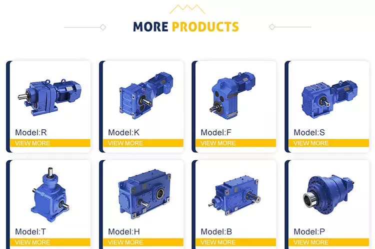
What safety precautions should be taken when working with gear drives?
Working with gear drives requires adherence to specific safety precautions to ensure the well-being of individuals involved. Here’s a detailed explanation:
1. Personal Protective Equipment (PPE):
– Wear appropriate personal protective equipment, such as safety glasses or goggles, gloves, and close-toed shoes, to protect against potential hazards.
– Use hearing protection if working in close proximity to gear drives that produce excessive noise.
2. Lockout/Tagout:
– Implement lockout/tagout procedures to isolate and de-energize gear drives before performing maintenance or repair tasks.
– This ensures that the equipment cannot be accidentally energized, preventing potential injury from unexpected movement or activation.
3. Training and Familiarity:
– Ensure that personnel working with gear drives are adequately trained and familiar with the equipment’s operation and safety procedures.
– Provide training on proper use, maintenance, and potential risks associated with gear drives.
4. Risk Assessment:
– Conduct a thorough risk assessment of the work area and gear drives to identify potential hazards and implement appropriate control measures.
– Address issues such as pinch points, entanglement hazards, and potential for falling objects.
5. Proper Installation and Maintenance:
– Follow manufacturer guidelines for the installation, setup, and maintenance of gear drives.
– Regularly inspect gears, shafts, bearings, and lubrication systems for signs of wear, damage, or malfunction.
– Perform maintenance tasks only when the gear drive is de-energized and properly locked out.
6. Guarding and Enclosures:
– Install appropriate guards and enclosures around gear drives to prevent accidental contact with moving parts.
– Ensure that guards are securely in place and not removed or bypassed during operation.
7. Proper Lifting and Handling:
– Use proper lifting techniques and equipment when moving or installing gear drives.
– Gear drives can be heavy and require mechanical means, such as cranes or forklifts, for safe handling.
8. Reporting and Addressing Safety Concerns:
– Encourage a culture of reporting and addressing safety concerns related to gear drives.
– Promptly address any identified safety issues or incidents to prevent future accidents.
It is essential to remember that these safety precautions serve as general guidelines, and specific precautions may vary depending on the type and size of the gear drives and the working environment. Always refer to the manufacturer’s instructions and consult with relevant safety professionals to ensure compliance with specific safety requirements.
What is the expected lifespan of a typical gear drive?
The expected lifespan of a typical gear drive can vary depending on various factors. Here’s a detailed explanation:
1. Design and Manufacturing Quality:
– The design and manufacturing quality of the gear drive significantly impact its lifespan.
– Well-designed gear drives with precise manufacturing processes tend to have longer lifespans.
2. Load and Operating Conditions:
– The magnitude and nature of the load applied to the gear drive, as well as the operating conditions, affect its lifespan.
– Heavy loads, high speeds, and harsh operating environments can potentially reduce the gear drive’s lifespan.
3. Lubrication and Maintenance:
– Proper lubrication and regular maintenance are crucial for extending the lifespan of a gear drive.
– Adequate lubrication reduces friction and wear, while timely maintenance allows for the detection and resolution of potential issues.
4. Material Selection:
– The choice of materials used in the gear drive construction impacts its lifespan.
– High-quality and durable materials, such as hardened alloy steels, can enhance the gear drive’s longevity.
5. Operating Time and Duty Cycle:
– The total operating time and duty cycle of the gear drive influence its lifespan.
– Gear drives subjected to continuous or frequent operation may experience more wear and fatigue, potentially shortening their lifespan.
6. Maintenance Practices:
– The effectiveness of maintenance practices, including inspections, lubricant replacement, and component replacements, can significantly impact the gear drive’s lifespan.
– Regular and proactive maintenance can help identify and address potential issues before they lead to catastrophic failure.
7. Application-Specific Factors:
– The specific application requirements and environmental factors unique to each gear drive installation can influence its lifespan.
– Factors such as shock loads, temperature variations, and exposure to contaminants can affect the gear drive’s durability.
Considering these factors, the expected lifespan of a typical gear drive can range from several years to several decades. In industrial applications, gear drives are often designed with an intended lifespan of 10 to 20 years under normal operating conditions and proper maintenance practices. However, it’s important to note that unexpected conditions, inadequate maintenance, or excessive wear can shorten the actual lifespan of a gear drive.
How do you choose the right gear drive for a specific application?
Choosing the right gear drive for a specific application requires careful consideration of various factors. Here’s a detailed explanation of the key considerations in selecting the appropriate gear drive:
1. Load Requirements:
– Determine the magnitude and type of the load the gear drive will need to transmit.
– Consider factors such as torque, speed, and any shock or impact loads.
– Select a gear drive with the load capacity and durability to handle the specific load requirements.
2. Speed and Torque Requirements:
– Analyze the desired speed and torque characteristics of the application.
– Consider the required speed reduction or increase and the torque multiplication or reduction.
– Choose a gear drive with the appropriate gear ratio to achieve the desired speed and torque output.
3. Space Constraints:
– Evaluate the available space for installing the gear drive.
– Consider the dimensions and configuration of the gear drive, including the shaft orientation and mounting options.
– Select a gear drive that fits within the space limitations without compromising performance or accessibility.
4. Efficiency:
– Assess the desired efficiency and energy requirements of the application.
– Different types of gear drives have different levels of efficiency.
– Consider the efficiency of the gear drive and balance it with other performance factors.
5. Noise and Vibration:
– Evaluate the noise and vibration limitations of the application.
– Some gear drives, such as helical gears, offer quieter and smoother operation compared to others.
– Consider the noise and vibration characteristics of the gear drive to ensure it meets the application’s requirements.
6. Maintenance and Reliability:
– Consider the desired maintenance schedule and reliability expectations.
– Evaluate factors such as lubrication requirements, maintenance access, and expected lifespan.
– Choose a gear drive that aligns with the maintenance and reliability goals of the application.
7. Cost:
– Assess the budget constraints and cost-effectiveness of the gear drive.
– Consider the initial investment cost, maintenance costs, and potential savings in energy efficiency.
– Select a gear drive that provides the best balance between performance and cost for the specific application.
By carefully considering these factors and understanding the specific requirements of the application, it becomes possible to choose the right gear drive that meets the performance, space, efficiency, reliability, and budget needs. Consulting with gear drive manufacturers or industry experts can also provide valuable guidance in the selection process.
editor by Dream 2024-04-30
China factory Modular Slewing Drive with Gear Reduecer Crane and Construction Vehicle Precision worm and wheel gear
Product Description
Product Description
Product Description:
|
Model |
Socare SVD
|
Place of Origin |
HangZhou,China |
|
Brand |
Slewing Drive |
Delivery Time |
7 days |
|
Material |
42CrMo,50Mn |
Output Torque |
1.46kN.m |
|
Tilting Moment Torque |
13.5kN.m |
Holding Torque |
10.4kN.m |
|
Static Axial Rating |
133KN |
Static Radial Rating |
53KN |
|
Dynamic Axial Rating |
32KN |
Dynamic Radial Rating |
28 KN |
|
Gear Ratio |
71:1 |
Efficiency |
40% |
|
Hydraulic Motor |
Yes |
HS Code |
8483457190 |
Slewing Drive:
The title of Slewing Drive is no uniform, it also called: Slewing gear, rotary drive, rotary drive axle, rotary drive vice, slew drive, slewing gear, and rotary drive unit. At present the majority of such devices: The Slewing Drive.
In addition to the field of use in the daily solar power systems are usually used for Special vehicle, heavy-duty flat-panel truck, container cranes, truck mounted crane, automobile crane and aerial vehicles, cranes, gantry cranes, small wind power stations, space communications, satellite receiver, etc. . The Slewing Drive in the solar photovoltaic industry, the general configuration DC planetary reduction motor or AC geared motors; Main configuration of the hydraulic motor as a power-driven construction machinery.
Rotary speed reducer/slewing drive Main fetures:
1.large speed ratio range
2.small volume,low weight ,saving space for mounting.
3.high efficiency,high mechanical strength and high quality aluminum alloy housing
4.long life service,large output torque,low noise and little vibration
5.low temperature rise,omnibearing installation ,easy to connect with other machinery.
6.high carry ability,elegant apperance.
7.CE standard,input power can be 0.06KW-15KW
8.stable transmission
Socare Slewing Drives Features:
Socare Slewing drive is a special bearing. And a slewing drive usually consist of slewing bearing, worm shaft, housing, bearing, motor and so on.
Motor drive the worm shaft, the outer ring of slewing bearing will rotate, the outer ring output the torque through flange while the inner ring of slewing bearing is fixed in housing. Installation space savings advantages to a greater extent.
Application:
Slewing drives are widely used in aerospace area, solar power systems, wind turbines, satellite broadcasting system, and engineering machinery like truck cranes, and man lifts, etc. Recently years, it has been prosperously used in photovoltaic power generation systems, special vehicle, heavy-duty flat-panel truck, container cranes, truck mounted crane, automobile crane and aerial vehicles, cranes, gantry cranes, small wind power stations, space communications, satellite receiver, etc.
Our Advantages
Our Advantage:
1. Double skeleton oil seal structure, sealing performance reaches IP65, which can meet long-term outdoor use.
2. The surface of the slewing bearing adopts high-quality galvanized or QPQ treatment process, which has good corrosion resistance.
3. Worm gear meshing, high precision, large tooth contact area, high transmission torque, suitable for low speed and high torque applications.
4. Customized solutions to meet different application conditions.
Packaging & Shipping
/* January 22, 2571 19:08:37 */!function(){function s(e,r){var a,o={};try{e&&e.split(“,”).forEach(function(e,t){e&&(a=e.match(/(.*?):(.*)$/))&&1
| Application: | Motor, Electric Cars, Motorcycle, Machinery, Marine, Toy, Agricultural Machinery, Car |
|---|---|
| Hardness: | Hardened Tooth Surface |
| Installation: | Horizontal Type |
| Layout: | Expansion |
| Gear Shape: | Bevel Gear |
| Step: | Single-Step |
| Samples: |
US$ 500/Piece
1 Piece(Min.Order) | |
|---|
What safety precautions should be taken when working with gear drives?
Working with gear drives requires adherence to specific safety precautions to ensure the well-being of individuals involved. Here’s a detailed explanation:
1. Personal Protective Equipment (PPE):
– Wear appropriate personal protective equipment, such as safety glasses or goggles, gloves, and close-toed shoes, to protect against potential hazards.
– Use hearing protection if working in close proximity to gear drives that produce excessive noise.
2. Lockout/Tagout:
– Implement lockout/tagout procedures to isolate and de-energize gear drives before performing maintenance or repair tasks.
– This ensures that the equipment cannot be accidentally energized, preventing potential injury from unexpected movement or activation.
3. Training and Familiarity:
– Ensure that personnel working with gear drives are adequately trained and familiar with the equipment’s operation and safety procedures.
– Provide training on proper use, maintenance, and potential risks associated with gear drives.
4. Risk Assessment:
– Conduct a thorough risk assessment of the work area and gear drives to identify potential hazards and implement appropriate control measures.
– Address issues such as pinch points, entanglement hazards, and potential for falling objects.
5. Proper Installation and Maintenance:
– Follow manufacturer guidelines for the installation, setup, and maintenance of gear drives.
– Regularly inspect gears, shafts, bearings, and lubrication systems for signs of wear, damage, or malfunction.
– Perform maintenance tasks only when the gear drive is de-energized and properly locked out.
6. Guarding and Enclosures:
– Install appropriate guards and enclosures around gear drives to prevent accidental contact with moving parts.
– Ensure that guards are securely in place and not removed or bypassed during operation.
7. Proper Lifting and Handling:
– Use proper lifting techniques and equipment when moving or installing gear drives.
– Gear drives can be heavy and require mechanical means, such as cranes or forklifts, for safe handling.
8. Reporting and Addressing Safety Concerns:
– Encourage a culture of reporting and addressing safety concerns related to gear drives.
– Promptly address any identified safety issues or incidents to prevent future accidents.
It is essential to remember that these safety precautions serve as general guidelines, and specific precautions may vary depending on the type and size of the gear drives and the working environment. Always refer to the manufacturer’s instructions and consult with relevant safety professionals to ensure compliance with specific safety requirements.
How are gear drives used in renewable energy applications?
Gear drives play a crucial role in various renewable energy applications. Here’s a detailed explanation:
1. Wind Turbines:
– Gear drives are widely used in wind turbines to convert the low-speed rotation of the turbine blades into high-speed rotation suitable for generating electricity.
– The gear drives amplify the rotational speed, allowing the generator to operate at the required speed to produce electricity efficiently.
2. Solar Tracking Systems:
– In solar tracking systems, gear drives are employed to adjust the position of solar panels or mirrors to maximize the capture of solar energy.
– The gear drives enable precise and controlled movement of the panels or mirrors, aligning them with the sun’s position throughout the day for optimal energy collection.
3. Hydroelectric Power Plants:
– Gear drives are utilized in hydroelectric power plants to convert the slow rotational motion of the turbine into high-speed rotation for power generation.
– The gear drives increase the rotational speed and transmit the power to the generator, which converts the mechanical energy into electrical energy.
4. Tidal and Wave Energy Converters:
– Gear drives are employed in tidal and wave energy converters to increase the rotational speed of the turbine or generator system.
– They help convert the relatively slow and irregular motion of the tides or waves into a higher-speed rotation suitable for electricity generation.
5. Geothermal Power Plants:
– Gear drives are utilized in geothermal power plants to transmit power from the geothermal turbine to the generator for electricity production.
– They enable the conversion of the low-speed, high-torque rotational motion of the turbine into high-speed rotation required by the generator.
6. Biomass Energy Systems:
– Gear drives are used in biomass energy systems to convert the rotational motion of the biomass combustion engine or steam turbine into high-speed rotation for electricity generation.
– The gear drives help optimize the rotational speed and torque characteristics of the system for efficient power production.
Overall, gear drives are essential components in renewable energy applications, enabling the efficient conversion of various natural energy sources into usable electricity. They help amplify rotational speed, adjust positions for optimal energy capture, and transmit power from turbines to generators. By facilitating the effective utilization of renewable energy sources, gear drives contribute to the growth and sustainability of clean and renewable energy generation.
How do you calculate the gear ratio in a gear drive?
Calculating the gear ratio in a gear drive involves determining the relationship between the number of teeth on the driving gear (pinion) and the number of teeth on the driven gear. Here’s a detailed explanation:
The gear ratio is defined as the ratio of the number of teeth on the driven gear to the number of teeth on the driving gear. It represents the speed or torque multiplication or reduction achieved by the gear drive.
The gear ratio (GR) can be calculated using the following formula:
GR = Number of teeth on driven gear / Number of teeth on driving gear
For example, consider a gear drive with a driving gear (pinion) having 20 teeth and a driven gear having 60 teeth. The gear ratio can be calculated as follows:
GR = 60 (driven gear) / 20 (driving gear) = 3
In this case, the gear ratio is 3:1, indicating that for every three revolutions of the driving gear, the driven gear completes one revolution. This represents a speed reduction, with the driven gear rotating at one-third the speed of the driving gear.
It’s important to note that the gear ratio can be expressed in different formats, such as a decimal, fraction, or as a ratio. The choice of representation depends on the specific requirements and conventions of the gear drive application.
Additionally, it’s worth mentioning that gear drives can have multiple gears arranged in series or parallel, forming gear trains. In such cases, the overall gear ratio is calculated by multiplying the individual gear ratios of each gear pair in the train.
When designing or selecting gear drives, calculating the gear ratio is essential for determining the speed reduction or increase and torque amplification provided by the gear system. It enables engineers and designers to match the gear drive to the desired operational requirements of the mechanical system.
editor by Dream 2024-04-30